Fuel cell module

A fuel cell and fuel cell unit technology, applied in the direction of fuel cells, fuel cell additives, fuel cell grouping, etc., can solve the problems of reduced reliability of gas sealing, leakage of oxygen-containing gas, increased assembly processes, etc., and achieve heat exchange efficiency Effects of rise, thermal independence, temperature rise, and assembly process reduction

Active Publication Date: 2010-02-24
KYOCERA CORP
View PDF4 Cites 0 Cited by
  • Summary
  • Abstract
  • Description
  • Claims
  • Application Information

AI Technical Summary

Problems solved by technology

[0009] Figure 26 In the shown conventional fuel cell module 100, the upper ends of the heat exchangers 120a, 120b and the bottom plate 142 of the oxygen-containing gas chamber 140 are joined by welding the flange portion, and the leakage of the oxygen-containing gas easily occurs from the welded portion 115.
If the oxygen-containing gas that has become high temperature through the heat exchanger leaks, not only the utilization rate of the oxygen-containing gas will decrease, but also the heat exchange efficiency and power generation efficiency will decrease due to heat loss, which will damage the high-efficiency thermal independent operation.
[0010] In addition, the casing 110 is separated up and down through the bottom plate 142 of the oxygen-containing gas chamber 140, so that not only the structure is complicated, but also the number of parts increases, and the assembly process of connecting and fixing and / or welding them also increases, and the storage cost and manufacturing cost of the parts increase.
[0011] Since there are relatively many welded parts in the housing of the conventional fuel cell module like this, the reliability of the gas seal is lowered, and there is also a problem of increasing the manufacturing cost.

Method used


Image

  • Fuel cell module
  • Fuel cell module
  • Fuel cell module

Examples


Embodiment Construction

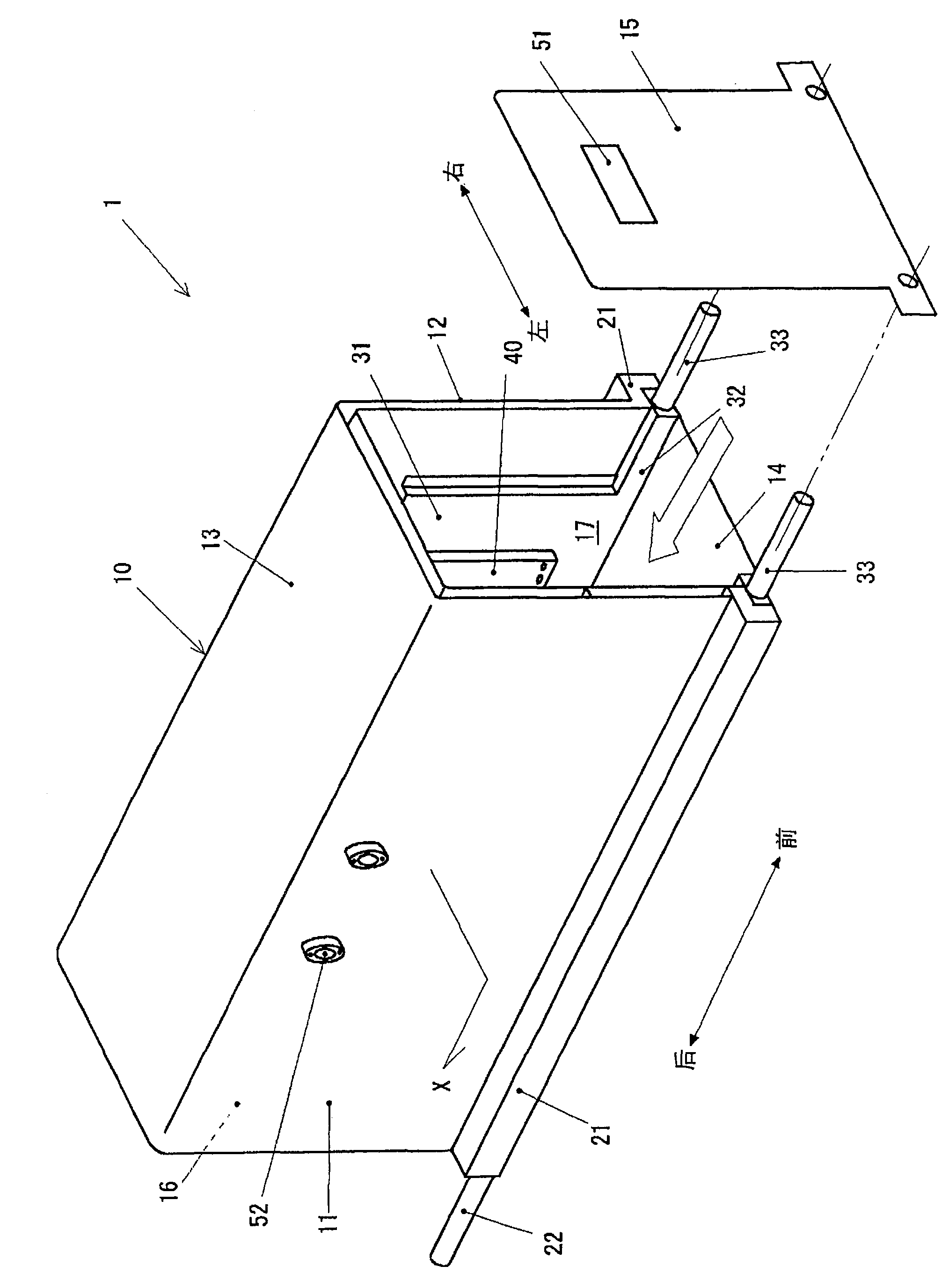
[0078] Embodiments of the present invention will be described below with reference to the drawings. The fixed oxide fuel cell module of the present invention is suitable for use in distributed power generation, especially a household fuel cell module performing a load following operation of 0.5 to 1.5 kW.

[0079] figure 1 It is an external perspective view of an embodiment of the fixed oxide fuel cell module of the present invention. The fuel cell module 1 includes a substantially rectangular parallelepiped casing 10 , and the casing 10 houses a power generation chamber 17 . figure 1It is not shown in the figure, but a battery pack (cell stack) in which a plurality of fixed oxide fuel cell units are arranged in a row is arranged in the power generation chamber 17, and a communication device (fuel gas box) and / or a reformer, etc. The fuel cell stack device constituted (details thereof will be described later). Hereinafter, regarding the housing 10 , the directions indicat...


PUM


Abstract

A fuel cell module which provides a structure of not causing gas leakage on an oxygen-containing gas flow path including a heat exchanger, and is reduced in costs. The fuel cell module comprises a power generating chamber housing a fuel cell, and an almost rectangular parallelepiped casing enclosing the power generating chamber, wherein the left and right walls and the top wall of the casing are hollow walls each forming a reaction gas flowing space by an outer shell member and an inner shell member provided in parallel with a specified gap between them, the outer shell member and the inner shell member are respectively formed in a U-shape in section, and a reaction gas introducing member is provided that suspends into the power generating chamber from the inner shell member of the top wall, communicates with the reaction gas flowing space, and introduces a reaction gas into the power generating chamber.

Description

technical field [0001] The present invention relates to a fuel cell module including a power generation chamber for accommodating a solid oxide fuel cell, and a case housing the power generation chamber. Background technique [0002] Figure 26 It is a schematic cross-sectional view showing a typical example of a conventional solid oxide fuel cell module 100 (Patent Documents 1, 2, etc.). [0003] Heat exchangers 120 a and 120 b are arranged on four or two sides of a substantially rectangular parallelepiped metal casing 110 in which the power generation chamber 111 is built. In the power generation chamber 111, there are, for example, four battery packs 80 in which fuel cells are arranged in one row, reformers 71 arranged above them, and manifolds 72 to which the battery packs 80 are mounted. . The communicator 72 is a fuel gas cartridge. An oxygen-containing gas chamber 140 is disposed on the power generation chamber 111, and a plurality of oxygen-containing gas introduc...

Claims


Application Information

Patent Timeline
Patent Type & Authority Patents(China)
IPC IPC(8): H01M8/04H01M8/12H01M8/0247H01M8/04014H01M8/04082H01M8/04089H01M8/24H01M8/2475H01M8/2485H01M8/249
CPCY02E60/521Y02E60/525Y02E60/50
Inventor 小野孝
Owner KYOCERA CORP
Why Eureka
Try Eureka