Balanced rotary engine

A rotating engine and balanced technology, applied in the direction of machines/engines, mechanical equipment, etc., can solve the problems of loss of efficiency, reduction of effective chamber mixed gas entry time, engine ventilation and compression, etc.

Inactive Publication Date: 2010-03-03
弗朗西斯科·哈维尔·路易斯·马丁内兹
View PDF6 Cites 0 Cited by
  • Summary
  • Abstract
  • Description
  • Claims
  • Application Information

AI Technical Summary

Problems solved by technology

[0002] Two-stroke engines developed to date include the use of nozzles as inlets for the combustion agent, which are placed inside the cylinders, significantly reducing the effective chamber, mixture entry time, ventilation and compression of the engine, so it loses effectiveness, does not Use of gas mixtures suitable for spontaneous explosions

Method used


Image

  • Balanced rotary engine
  • Balanced rotary engine
  • Balanced rotary engine

Examples


Embodiment Construction

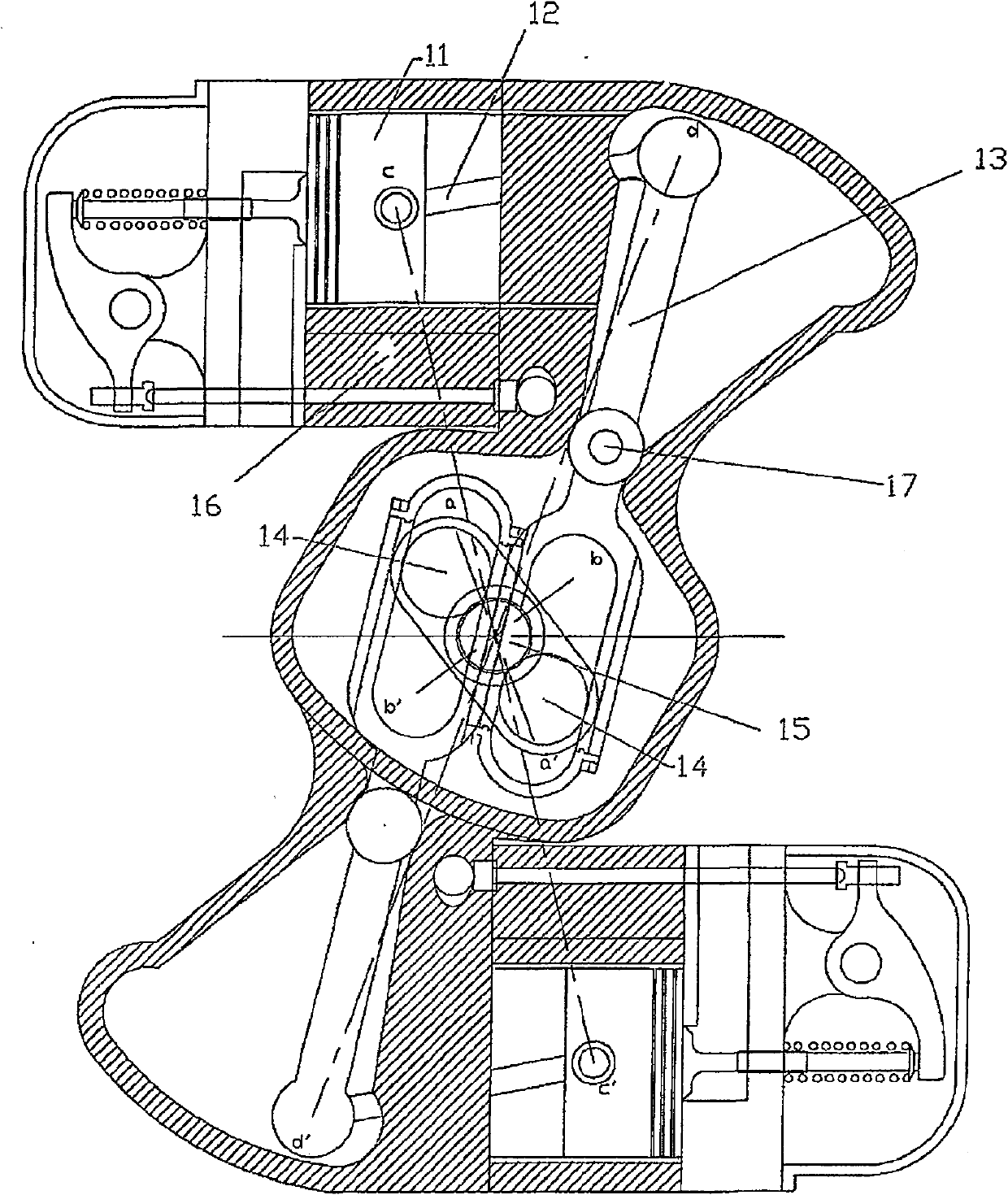
[0026] The present invention relates to a balanced rotary engine consisting of a rotary engine including tangential pistons which improve engine performance, facilitate lubrication of engine components, and enable use at high speeds of rotation. The composition of the components is such that the engine is self-powered, and air or a mixture is drawn directly from the rear of the cylinder and injected into the combustion chamber of said cylinder or a combustion chamber adjacent to the cylinder, which air or mixture is suitable for full use of combustion Two-stroke operation of the chamber, even mixtures that spontaneously explode once a moderately high pressure is reached (Diesel cycle).

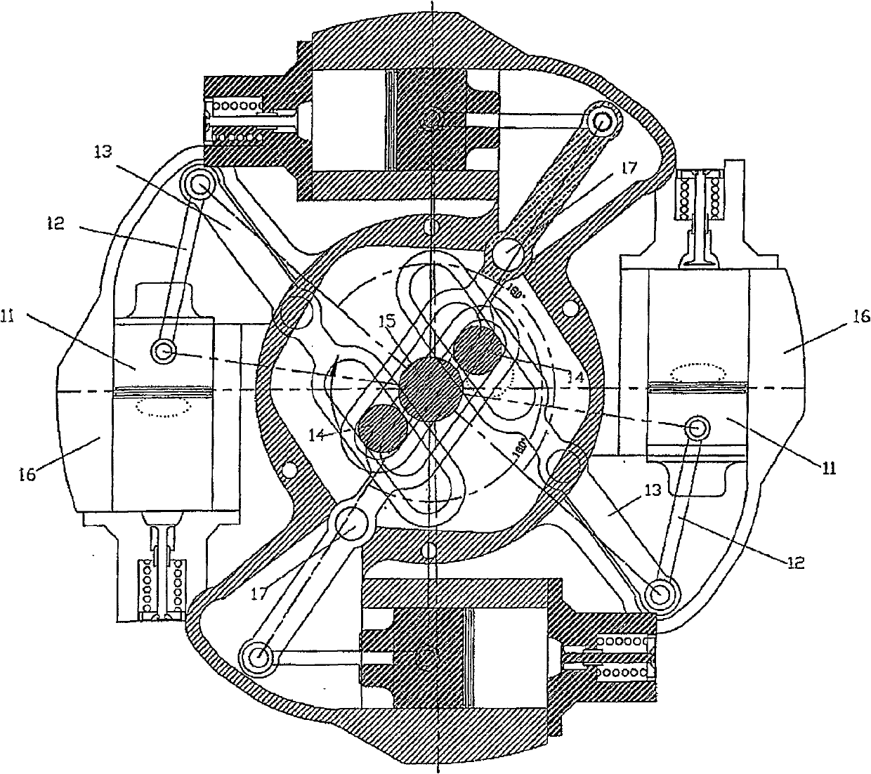
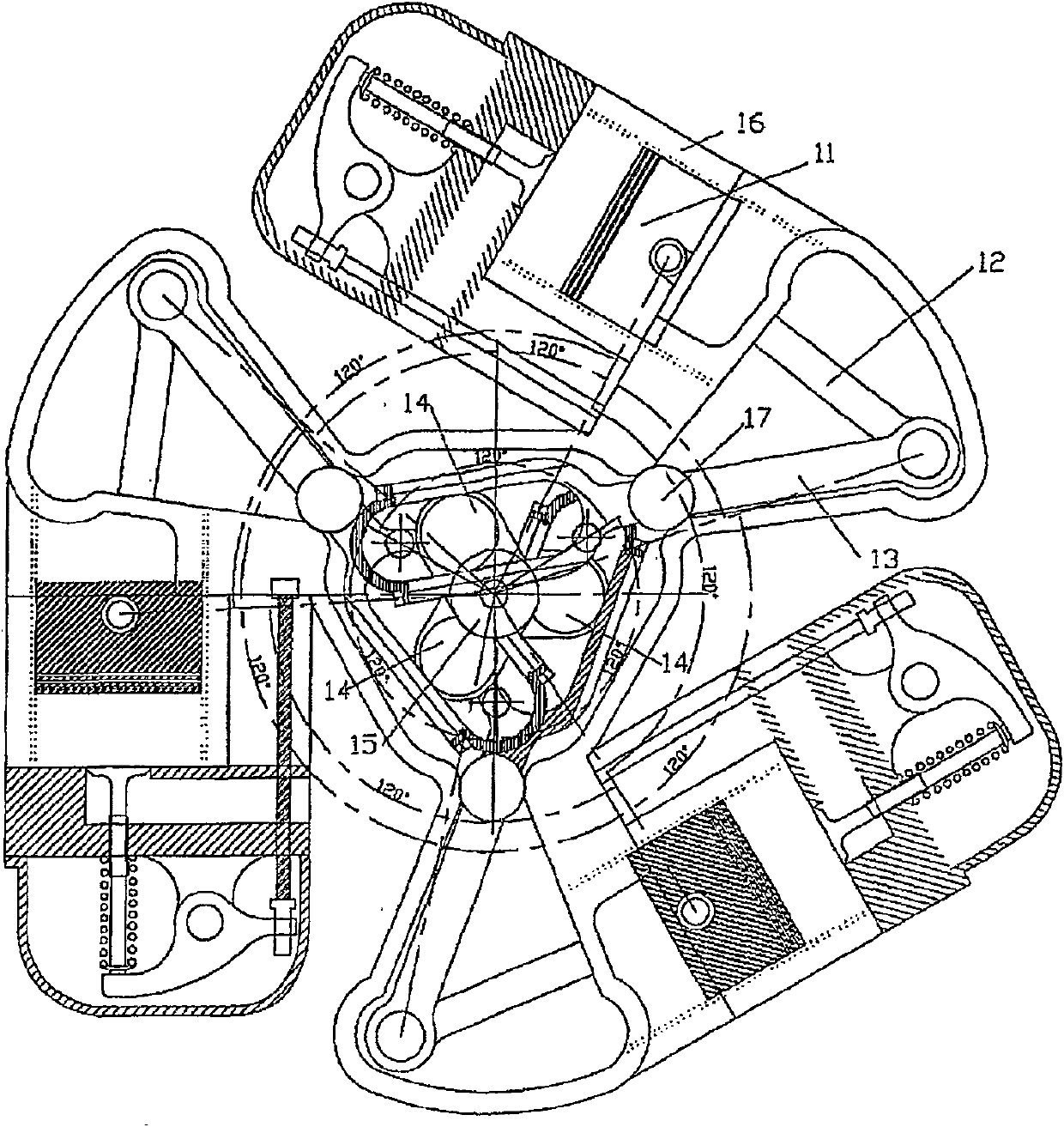
[0027] As shown in the accompanying drawings, there are two preferred embodiments of the balanced rotary engine. The first embodiment shows a balanced rotary engine ( figure 1 , figure 2 and image 3 ), while the second embodiment shows a self-powered balanced rotary engine ( Figure 4 , ...


PUM


Abstract

The invention relates to a balanced rotary engine consisting of a rotary engine comprising tangential pistons which improve engine performance, facilitate the lubrication of the engine components, enable the use thereof at high revolutions and condition same for two-stroke operation with full use of the combustion chamber, even with mixtures (diesel cycle) which explode spontaneously upon reachinghigh compressions with a suitable volume. According to the invention, the components are structured such that (i) the engine can also be self-powered and (ii) the air or mixture is drawn directly from the rear of the cylinder and, subsequently, injected into the combustion chamber of said cylinder or of the cylinder adjacent thereto.

Description

technical field [0001] The present invention relates to rotary engines, and more particularly, the present invention relates to a balanced rotary engine. Background technique [0002] Two-stroke engines developed to date include the use of nozzles as inlets for the combustion agent, which are placed inside the cylinders, significantly reducing the effective chamber, mixture entry time, ventilation and compression of the engine, so it loses effectiveness, does not Suitable for the use of gas mixtures that explode spontaneously. [0003] Likewise, rotary engines currently under development include tangential pistons, with opposing pistons connected to the same pivot or journal of the crankshaft, in such a way that the internal Movement of components (pistons, connecting rods or rotary rods) is not symmetrical, creating vibrational loads. Also, these components are housed in a single chamber, making it difficult to lubricate them when the medium used for lubrication is moved ...

Claims


Application Information

Patent Timeline
Patent Type & Authority Patents(China)
IPC IPC(8): F02B75/26F02B75/32
Inventor 弗朗西斯科·哈维尔·路易斯·马丁内兹
Owner 弗朗西斯科·哈维尔·路易斯·马丁内兹
Why Eureka
Try Eureka