
Motor rotor and its making method

A technology of motor rotor and manufacturing method, applied in the field of motor rotor and its manufacturing, to achieve the effects of reducing bending moment, reducing rotational unbalance, and improving flatness and closure

Inactive Publication Date: 2006-06-14
DELTA ELECTRONICS INC
View PDF0 Cites 0 Cited by
  • Summary
  • Abstract
  • Description
  • Claims
  • Application Information

AI Technical Summary

Problems solved by technology

[0005] In order to solve the above problems, the present invention proposes a motor rotor and its manufacturing method to greatly improve the flexibility of the rubber magnets of the motor rotor, and make the joints of the magnets bent more flat, thereby making the magnetic field evenly distributed and avoiding chattering , reduced operating efficiency, high-frequency noise and other adverse phenomena

Method used


Image

  • Motor rotor and its making method
  • Motor rotor and its making method
  • Motor rotor and its making method

Examples


Embodiment Construction

[0021] In order to make the above and other purposes, features, and advantages of the present invention more comprehensible, a preferred embodiment is specifically cited below, together with the accompanying drawings, for a detailed description:

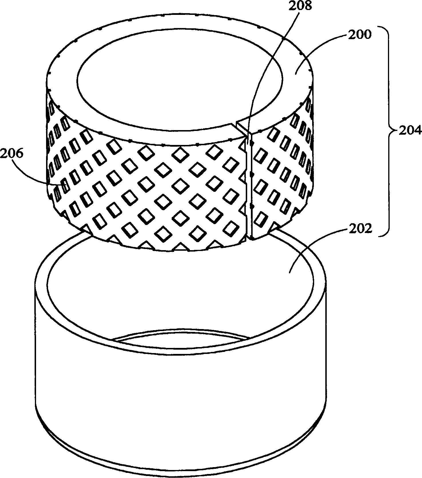
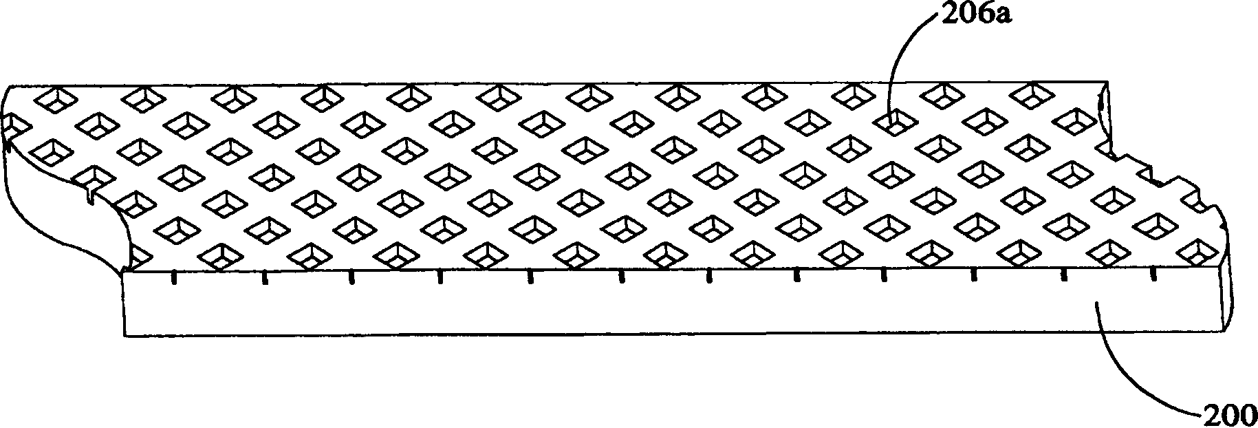
[0022] Please refer to figure 2 , which is a structural schematic diagram of a motor rotor in a preferred embodiment of the present invention. Such as figure 2 As shown, the motor rotor 204 of the present invention is composed of a magnetically permeable yoke 202 and a rubber magnet 200 disposed inside the magnetically permeable yoke 202 . The magnetic yoke 202 is made of a conductive material such as iron, and its shape is, for example, an annular shape. To manufacture the motor rotor 204 of the present invention, firstly, select a rubber magnet 200 formed of a strip-shaped rubber tape material with a flat surface. Next, one or more patterns 206 are formed on one side surface of the rubber magnet 200 as a surface intended to fa...


PUM


Abstract

A motor rotor is composed of a magnetically permeable yoke and a rubber magnet arranged inside the magnetically permeable yoke, wherein the surface of the rubber magnet facing the magnetically permeable yoke has one or more patterns. The manufacturing method of this motor rotor selects a rubber magnet with a flat surface, forms one or more patterns on one side of the rubber magnet, and then bends the aforementioned rubber magnet in such a way that the patterned surface of the rubber magnet faces outward Make it into the shape corresponding to the inner surface of the magnetic yoke iron, and then place the rubber magnet in the magnetic yoke iron.

Description

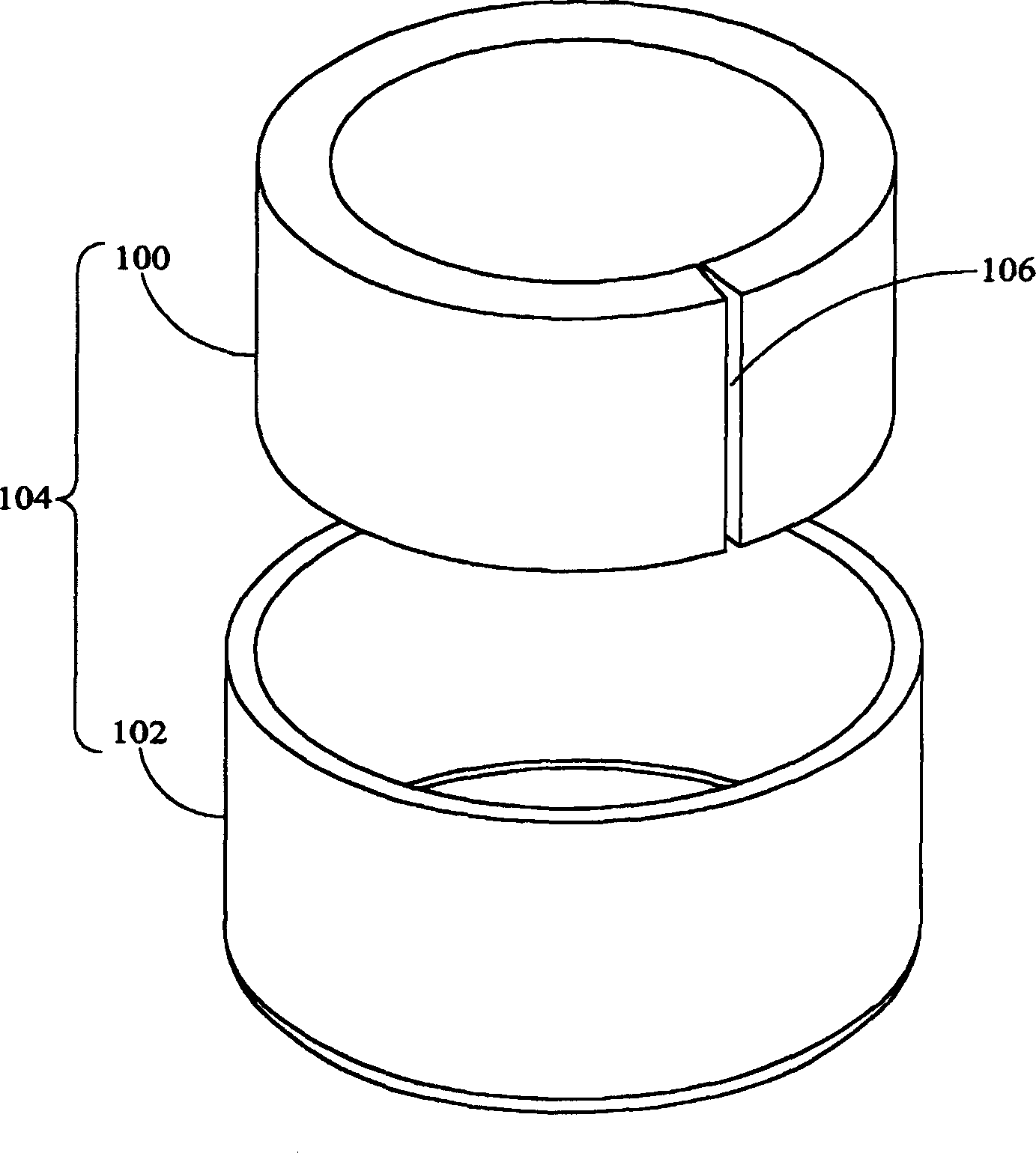
technical field [0001] The present invention relates to a motor rotor and a manufacturing method thereof, in particular to a method of forming a pattern on the outer surface of a rubber magnet of the motor rotor to improve the flexibility of the rubber magnet. Background technique [0002] In rotating mechanical structures such as fans / motors, magnets are one of the main components. In order to reduce the cost of the motor structure, low-cost rubber magnets are currently used in rotating machine structures such as motors. [0003] Please refer to figure 1 , which is a structural schematic diagram of a motor rotor currently using rubber magnets. Such as figure 1 As shown, in the existing motor manufacturing process using rubber magnets 100, the assembly method of the motor rotor 104 is to directly bend the strip-shaped rubber magnets 100 of predetermined specifications into a ring shape, and then bend the ring-shaped rubber magnets 100 is pressed into a magnetic yoke 102 ...

Claims


Application Information

Patent Timeline
Patent Type & Authority Patents(China)
IPC IPC(8): H02K1/22H02K15/02
Inventor 叶东昌林永彬
Owner DELTA ELECTRONICS INC
Learn More