Solid liquid two-phase odour purifier

A purifier and odor technology, applied in deodorization, disinfection, etc., can solve the problems of low deodorization efficiency, uneven air distribution, large volume, etc., and achieve high deodorization efficiency, uniform air distribution, and small volume Effect

Inactive Publication Date: 2007-07-18
HUAZHONG UNIV OF SCI & TECH
View PDF0 Cites 3 Cited by
  • Summary
  • Abstract
  • Description
  • Claims
  • Application Information

AI Technical Summary

Problems solved by technology

A more commonly used purifier consists of a tank, an air inlet, an air outlet, and a simple solid-phase adsorp

Method used


Image

  • Solid liquid two-phase odour purifier

Examples


Embodiment Construction

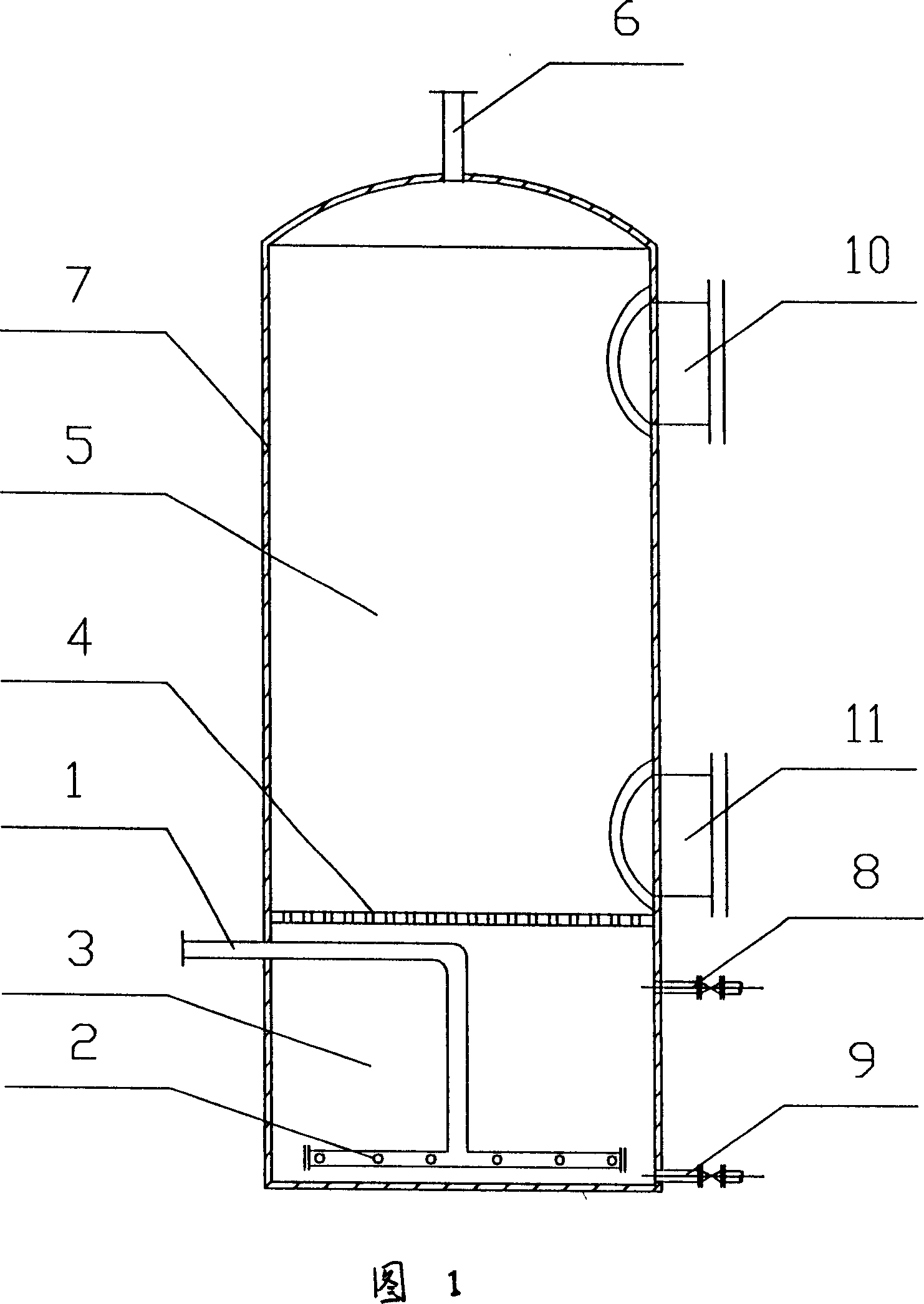
[0009] As shown in Figure 1, the solid-liquid two-phase odor purifier of the present invention consists of an odor inlet pipe 1, an air distribution pipe 2, a liquid phase adsorption chamber 3, an air distribution plate 4, a solid phase adsorption chamber 5, and an odor discharge pipe 6 Composed of a purifier tank 7, the upper and lower parts of the liquid phase adsorption chamber 3 are respectively provided with adsorption liquid inlet holes 8 and adsorption liquid outlet holes 9, and the upper and lower parts of the solid phase adsorption chamber 5 are respectively provided with solid phase adsorption fillers Inlet hole 10, solid phase adsorption packing outlet hole 11. The tank body 7 of the purifier adopts an integrated design, cylindrical, and the gas distribution plate 4 divides the purifier into upper and lower parts. The upper part is the solid phase adsorption chamber 5, and the lower part is the liquid phase adsorption chamber 3; A large number of micropores, the liq...


PUM


Abstract

A solid-liquid apparatus with cylindrical shape for cleaning the foul gas is a cylindrical main body divided into upper solid-phase adsorption chamber and lower liquid-phase one by a microporous gas distributing plate and with a foul gas inlet tube in said liquid-phase chamber, a clean gas outlet tube on the top, solid filler inlet and outlet, and liquid inlet and outlet.

Description

technical field [0001] The invention belongs to sewage treatment equipment, in particular, it relates to a purifier, especially a solid-liquid two-phase odor purifier. Background technique [0002] Sewage treatment has become an important issue in environmental protection, and a large amount of odor is produced during the biological treatment of sewage and the collection and storage of sewage. Existing this type of odor treatment equipment is more, and the purifier that is used for odor treatment also has many. A more commonly used purifier consists of a tank, an air inlet, an air outlet, and a simple solid-phase adsorption chamber (or liquid-phase adsorption chamber). Corrosion, low deodorization efficiency and other problems. Contents of the invention [0003] The object of the present invention is to provide a purifier that overcomes the above-mentioned defects, that is, a solid-liquid two-phase odor purifier, which is not easy to block, small in size, uniform in gas ...

Claims


Application Information

Patent Timeline
IPC IPC(8): A61L9/014
Inventor 解清杰吴晓辉黄卫红
Owner HUAZHONG UNIV OF SCI & TECH
Why Eureka
Try Eureka