Sucker rod rope suspension apparatus

A sucker rod and suspension rope technology, applied in drill pipe, production fluid, drilling equipment, etc., can solve problems such as single function, achieve the effect of advanced principle, novel structure and prolong service life

Inactive Publication Date: 2007-07-18
HENAN XINYU PETROLEUM MACHINERY MFG
View PDF0 Cites 14 Cited by
  • Summary
  • Abstract
  • Description
  • Claims
  • Application Information

AI Technical Summary

Problems solved by technology

It has the advantage of simple structure, but its disadvantage is that it has single function. It is only used as a connecting piece between the donkey head wire rope hair flap of the pumping unit and the sucker rod. During the pumping process of the pumping unit, it can only move up and down mechanically. The eccentricity and inclination of the sucker rod and the production wellhead caused the eccentric wear of the packing of the polished rod sealer, and the eccentric wear of the sucker rod coupling and the tubing without any preventive function

Method used


Image

  • Sucker rod rope suspension apparatus
  • Sucker rod rope suspension apparatus

Examples


Embodiment Construction

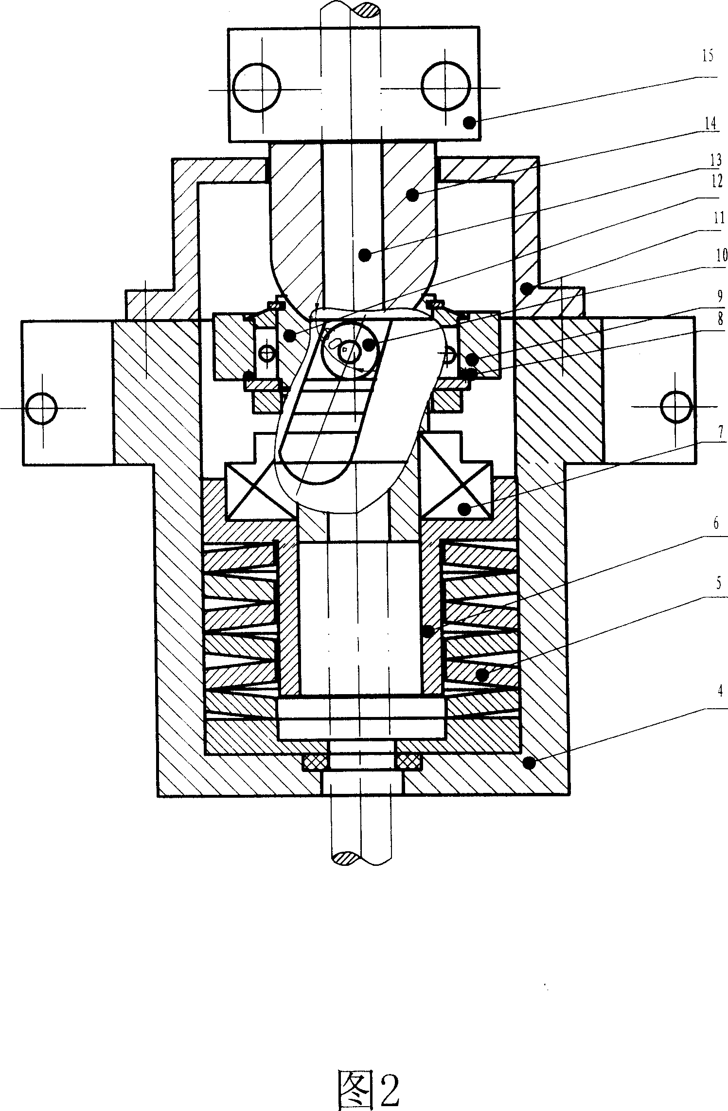
[0009] In the embodiment of Fig. 2, the casing 4, the load bearing body 6, the ratchet 9, the transmission member 10, the upper cover 11, the sucker rod seat 12, the universal joint 14, the polished rod clip 15 and other components are obtained by machining. The mutual positional relationship of each component is: first put several disc springs 5 ​​into the housing 4 in a back-to-back or face-to-face combination, and then insert the load-bearing body 6 into the inner hole of the disc springs 5 ​​. Then install the ratchet 9 assembly, put the sucker rod base 12 on the platform, install the inverted claw 8 and the ratchet 9 on its outer edge, fix the transmission part 10 on the outer edge of the ratchet, and then turn the assembly 180 °, insert the lower end into the inner hole of the axial bearing 7, then install the transmission part 10 in the chute of the housing 4, and then install the universal joint 14, the upper cover 11, and the polished rod clamp 15.


PUM


Abstract

The sucker rod rotating rope hanger consists of a casing, a butterfly spring, a bearing, a bearer, a sucker rod seat, a ratchet wheel, a driving member, and other parts. Its operation principle is that during the sucker rod moves upwards, the increased sucker rod weight and the compressed spring make the driving member rotates clockwise while moving downwards; during the sucker rod moves downwards, the decreased sucker rod weight and the extending spring and the single direction rotating ratchet wheel make the driving member rotates counterclockwise idly; so that each motion period of the sucker rod makes the sucker rod under the action of the rope hanger rotate by some angle.

Description

Technical field: [0001] The invention relates to a rope suspension device for an oil field sucker rod, in particular to a rope suspension device capable of slowly rotating the sucker rod. Background technique: [0002] Currently known rope suspension devices are composed of a body, a baffle plate, a stopper and the like as shown in FIG. 1 . It has the advantage of simple structure, but its disadvantage is that it has single function. It is only used as a connecting piece between the donkey head wire rope hair flap of the pumping unit and the sucker rod. During the pumping process of the pumping unit, it can only move up and down mechanically. The eccentricity and inclination of the sucker rod and the production wellhead caused the eccentric wear of the packing of the polished rod sealer, and the eccentric wear of the sucker rod coupling and the tubing, but there is no preventive function. Invention content: [0003] In order to overcome the shortcomings of the existing ro...

Claims


Application Information

Patent Timeline
Patent Type & Authority Applications(China)
IPC IPC(8): E21B19/02E21B43/00
Inventor 杜振宇廖大林何卫陆艳丽王勇
Owner HENAN XINYU PETROLEUM MACHINERY MFG
Why Eureka
Try Eureka