Concave surface and convex surface detecting method and device of object with concave surface and convex surface being mirror reflection surfaces

A specular reflection and detection device technology, applied in the direction of measuring devices, optical devices, instruments, etc., can solve the problems of high cost and unsuitable application

Inactive Publication Date: 2014-02-26
新乡市天光科技有限公司
View PDF8 Cites 0 Cited by
  • Summary
  • Abstract
  • Description
  • Claims
  • Application Information

AI Technical Summary

Problems solved by technology

[0004] The object of the present invention is to provide a method for detecting the concave-convex surface of an article whose concave-convex surface is a specular reflection surface, so as to solve the problem that the detection method for detecting the curvature of the blade in the prior art has a high cost and is not suitable for being used only for judging the concave-convex surface of the article And the technical problem of the detection place that needs to carry out batch detection; Simultaneously, the present invention also provides a kind of detection device that is used to implement above-mentioned detection method

Method used


Image

  • Concave surface and convex surface detecting method and device of object with concave surface and convex surface being mirror reflection surfaces
  • Concave surface and convex surface detecting method and device of object with concave surface and convex surface being mirror reflection surfaces
  • Concave surface and convex surface detecting method and device of object with concave surface and convex surface being mirror reflection surfaces

Examples


Embodiment 1

[0033] The object to be tested here is glass, one side of the glass is concave, and the other side is convex. The detection method in this embodiment specifically includes the following steps:

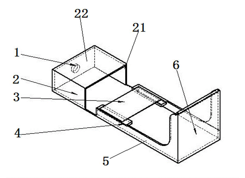
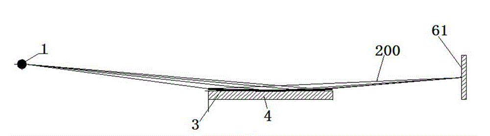
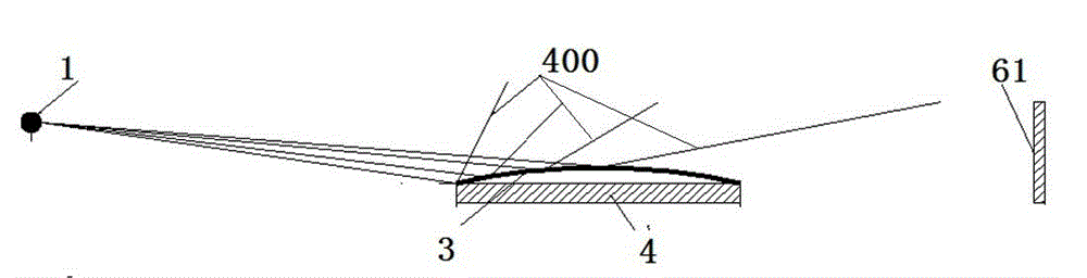
[0034](1) Use a light source that emits divergent light at the set irradiation position to irradiate the test surface of the glass to be tested at the set detection position. The surface receives the reflected light reflected from the surface to be measured to the projection surface,

[0035] (2) Observe the projection surface, if there is no image on the projection surface, the glass to be tested is unqualified; if there is an image on the projection surface, combine the image with the light source located at the set irradiation position to irradiate at the set detection position The preset standard part at the location is compared with the standard imaging formed by projecting on the projection surface at the set receiving position to determine whether the surface to be measured is c...

Embodiment 2

[0048] The detection method in this embodiment is different from the detection method in Embodiment 1 in that the detection method in this embodiment is only suitable for detecting mirror-reflective articles with both concave and convex surfaces, and specifically includes the following steps:

[0049] (1) The object to be tested has a first surface to be tested and a second surface to be tested with different concave and convex properties. The two surfaces to be tested are both specular reflective surfaces. The first surface to be measured of the object to be tested at the fixed detection position, and at the same time, the projection surface at the set position is used to receive the reflected light reflected from the first surface to be measured to the projection surface, and the projection surface is observed. If the projection surface If there is no image on the projection surface, the item to be tested is unqualified. If there is an image on the projection surface, record ...


PUM


Abstract

The invention discloses a concave surface and convex surface detecting method and device of an object with the concave surface and the convex surface being mirror reflection surfaces. The detecting method comprises the steps that 1 a light source which is located at a set irradiation position and can emit divergent light is used for irradiating a surface to be detected, the surface to be detected is the surface of an object to be detected, the object to be detected is located at a set detection position, the surface to be detected is a mirror reflection surface, and meanwhile, a projection surface at a set receiving position is used for receiving reflection light which is reflected onto a projection surface through the surface to be detected; 2 the projection surface is observed, if no image is formed on the projection surface, the object to be detected is unqualified; if an image is formed on the projection surface, the image is compared with a standard image and whether the surface to be detected is a concave surface or a convex surface is judged. The difference between the image formed on the projection surface when the light source irradiates the concave surface and the image formed on the projection surface when the light source irradiates the convex surface is obvious, a detection personnel can directly observe the difference through naked eyes and the detecting cost is low.

Description

technical field [0001] The invention relates to a detection method and a detection device for a concave-convex surface of an article whose concave-convex surface is a specular reflection surface. Background technique [0002] The raw material used for the display protection screen of electronic products is float glass. During the production process of float glass, due to the limitation of the production process, a certain amount of tin will penetrate into one side of the glass to form a tin surface, and the glass is tempered. During processing (that is, to increase the strength of the glass, chemical methods are used to form compressive stress on the glass surface. When the tempered glass is subjected to external forces, it must first offset the stress of the glass surface layer, which improves the bearing capacity of the glass and enhances the wind resistance of the glass itself. Pressure resistance, cold and heat resistance, impact resistance and wear resistance, etc.) usu...

Claims


Application Information

Patent Timeline
Patent Type & Authority Applications(China)
IPC IPC(8): G01B11/24
Inventor 杨振发何清江田新建
Owner 新乡市天光科技有限公司
Why Eureka
Try Eureka