Self-regulating type hydrodynamic gas elastic foil bearing

An elastic foil, self-adjusting technology, applied in the direction of bearings, shafts and bearings, mechanical equipment, etc., can solve the problems of dynamic pressure gas elastic foil bearing load capacity reduction, air leakage, etc., to improve load capacity, reduce leakage, The effect of enhanced stability

Inactive Publication Date: 2007-07-18
HARBIN INST OF TECH
View PDF0 Cites 24 Cited by
  • Summary
  • Abstract
  • Description
  • Claims
  • Application Information

AI Technical Summary

Problems solved by technology

[0003] The purpose of the present invention is to provide a self-adjusting dynamic pressure gas elastic foil bearing, which can solve the problem of air leakage from the edges of both sides of the flat foil during the operation of the existing dynamic pressure gas elastic foil bearing, resulting in dynamic pressure The Problem of Reduced Load Capacity of Gas Elastic Foil Bearings

Method used


Image

  • Self-regulating type hydrodynamic gas elastic foil bearing
  • Self-regulating type hydrodynamic gas elastic foil bearing
  • Self-regulating type hydrodynamic gas elastic foil bearing

Examples


specific Embodiment approach 1

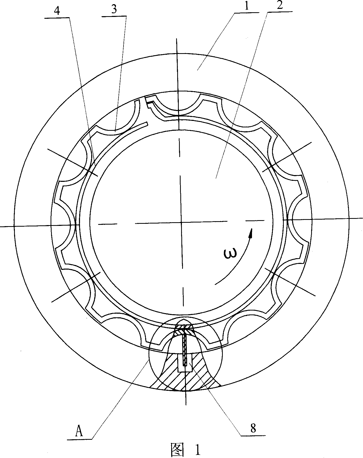
[0007] Specific embodiment 1: This embodiment is described in conjunction with Fig. 1 to Fig. 18. This embodiment is composed of a housing 1, a corrugated foil 3, a flat foil 4 and a self-regulator 5; the flat foil 4 is installed in the housing 1, between the housing 1 and the flat foil 4, there are corrugated foils 3 that are respectively in contact with the housing 1 and the flat foil 4; the self-regulator 5 is installed in the housing 1 and located in the housing 1 and the corrugated foil 3 or between the shell 1 and the flat foil 4, the number of self-regulators 5 is determined according to actual production needs, and the self-regulators 5 are distributed along the inner wall of the shell 1 to ensure the bearing capacity .

[0008] When in use, the bearing is mounted on the rotating shaft 2 to ensure the clearance fit between the flat foil 4 and the rotating shaft 2 .

specific Embodiment approach 2

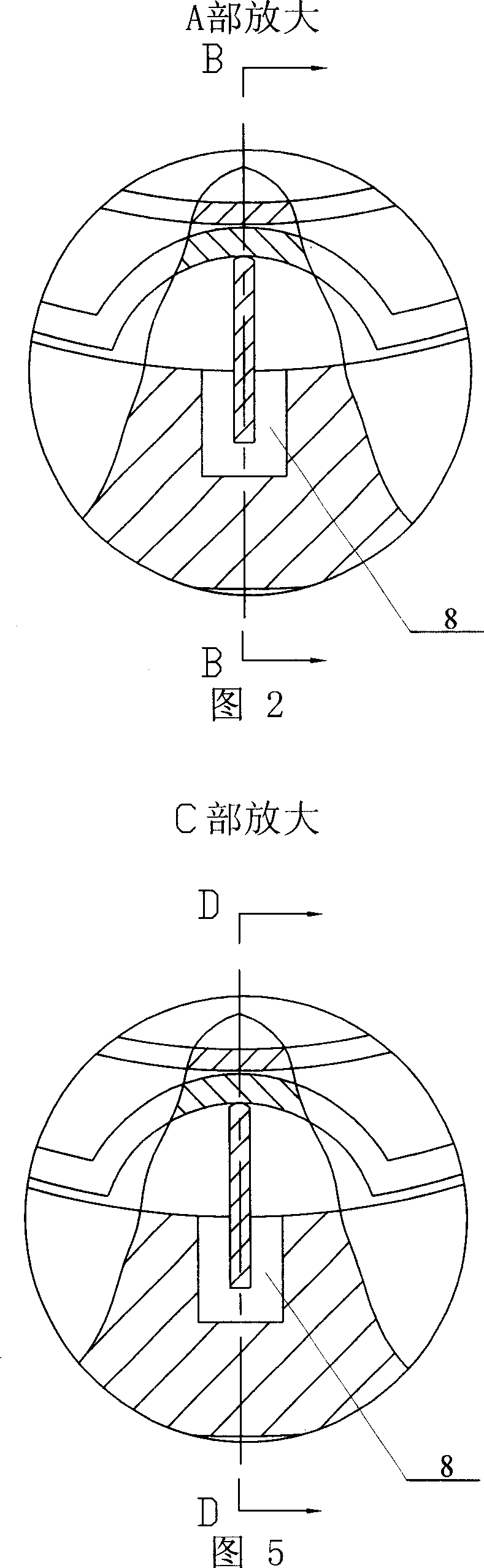
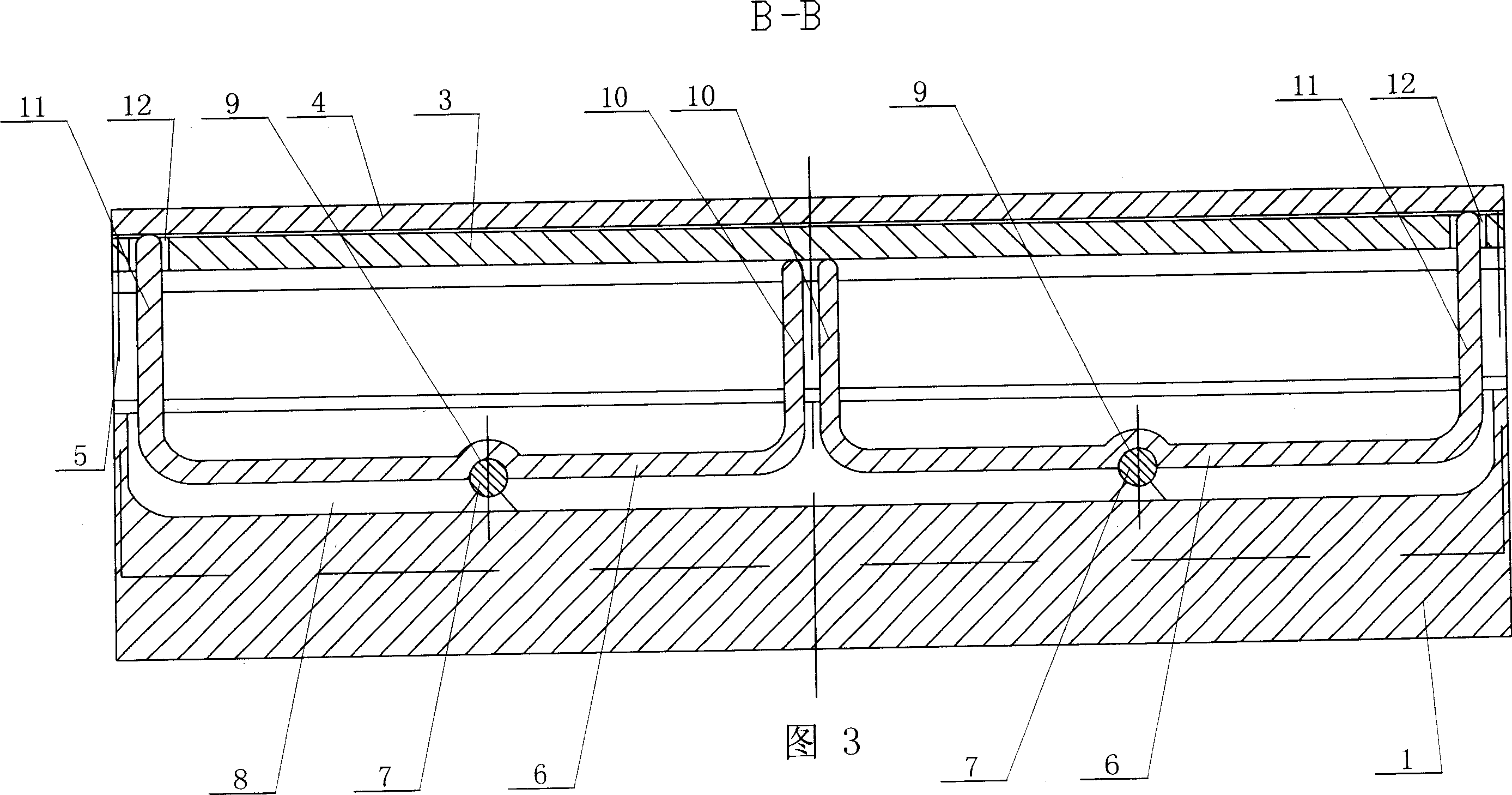
[0009] Specific Embodiment 2: This embodiment is described with reference to FIGS. 1 to 3. The self-regulator 5 of this embodiment is located between the housing 1 and the flat foil 4. The self-regulator 5 is composed of two first U-shaped rods 6 and Composed of two first cylindrical hinge supports 7, the inner wall of the housing 1 is provided with a first long slot 8 in the axial direction, and two first U-shaped rods are installed in the first long slot 8 in the axial direction 6. The lower end of each first U-shaped bar 6 corresponds to a first cylindrical hinge support 7 respectively, and the upper end of the first cylindrical hinge support 7 is installed on the first circle at the lower end of the corresponding first U-shaped bar 6. In the arc-shaped pit 9, the lower end of the first cylindrical hinge support 7 is affixed to the bottom end surface of the first long groove 8, and the ends of the two radial rods 10 adjacent to the two first U-shaped rods 6 are respectively ...

specific Embodiment approach 3

[0010] Specific Embodiment 3: This embodiment is described in conjunction with FIGS. 4 to 6. The self-regulator 5 of this embodiment is located between the housing 1 and the corrugated foil 3. The self-regulator 5 is composed of two second U-shaped rods 14 and Composed of two second cylindrical hinge supports 15, the inner wall of the housing 1 has a second long slot 16 in the axial direction, and the second long slot 16 is equipped with two second U-shaped rods in the axial direction 14. The lower end of each second U-shaped bar 14 corresponds to a second cylindrical hinge support 15, and the upper end of the second cylindrical hinge support 15 is mounted on the second circular arc at the lower end of the corresponding second U-shaped bar 14. In the pit 17, the lower end of the second cylindrical hinge support 15 is affixed to the bottom end surface of the second long groove 16, and the ends of the two radial rods 18 of each second U-shaped rod 14 are respectively connected to...


PUM


Abstract

The invention is a self-adjusting aerodynamic foil bearing, relating to an aerodynamic foil bearing, comprising casing, ripple foil and plane foil, where the plane foil is arranged in the casing, and the ripple foil is arranged between the casing and the plane foil and contacts with them; and the invention also comprises a self-adjustor, arranged in the casing and located between the casing and the ripple or plane foil. By adding a self-adjustor to the original aerodynamic foil bearing, the highest pressure of lubricating air membrane is transferred through the self-adjustor to the two sides of the plane foil to deform it so as to largely reduce leakage of lubricating airflow from two side edges of the plane foil, improving bearing capability of the bearing.

Description

technical field [0001] The invention relates to a dynamic pressure gas elastic foil bearing. Background technique [0002] At present, the dynamic pressure gas elastic foil bearing has been developed to the third generation, and each generation only appropriately changes the length and width of the corrugated foil circumferential direction of the dynamic pressure gas elastic foil bearing, and changes the axial length and width of the corrugated foil. The width or pitch length and wave height of the corrugated foil are changed, but the structure of the dynamic pressure gas elastic foil bearing is not changed. During the operation of the modified gas dynamic pressure elastic foil bearing, there is a problem that a large amount of air leaks from the edges on both sides of the flat foil, resulting in a reduction in the load carrying capacity of the gas dynamic pressure gas elastic foil bearing. Contents of the invention [0003] The purpose of the present invention is to prov...

Claims


Application Information

Patent Timeline
Patent Type & Authority Applications(China)
IPC IPC(8): F16C32/06
Inventor 刘占生许怀锦
Owner HARBIN INST OF TECH
Why Eureka
Try Eureka