Backlight module for flat display device
A flat display and backlight module technology, applied in optics, nonlinear optics, instruments, etc., can solve problems such as laborious, insurmountable bright bands, and time-consuming
- Summary
- Abstract
- Description
- Claims
- Application Information
AI Technical Summary
Problems solved by technology
Method used
Image
Examples
Embodiment 1
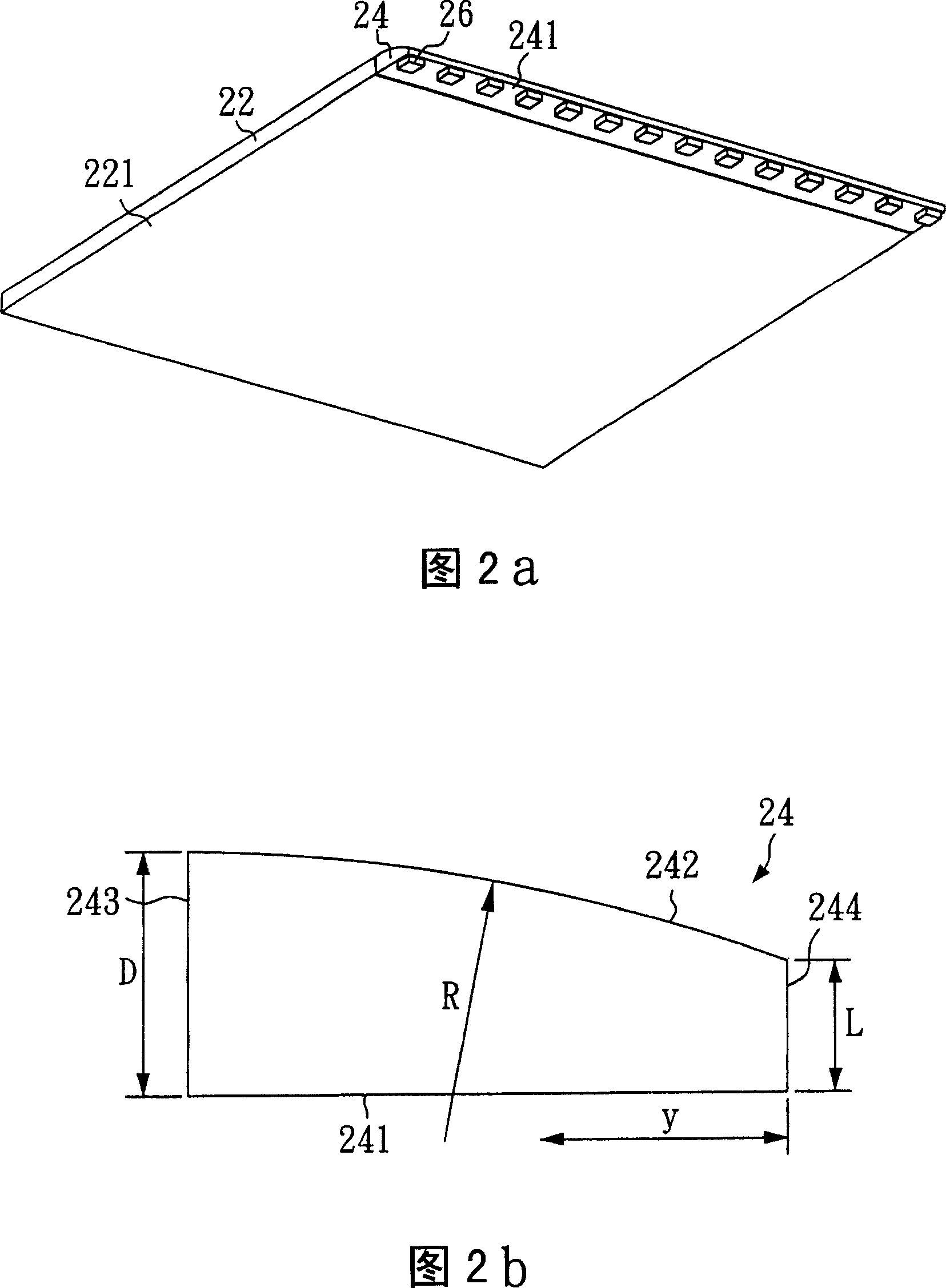
[0034] Please refer to FIG. 2 a , which is a three-dimensional schematic diagram of a preferred embodiment of the backlight module of the present invention. In FIG. 2 a , the light guide plate 22 is a square plate, one side of the light guide plate 22 is adjacent to a columnar optical element 24 , and a plurality of light emitting diodes 26 are disposed on the bottom surface 241 of the columnar optical element 24 . Thus, the light emitted by the LED 26 can be guided into the light guide plate 22 through the columnar optical element 24 .
[0035] Please refer to FIG. 2b, which is a cross-sectional view of the cylindrical optical element 24 in FIG. 2a. As shown in FIG. 2b, the cylindrical optical element 24 includes a total reflection surface 242, a bottom surface 241, a first side 243 and a second side 2440. The first side 243 of the cylindrical optical element 24 is connected to the side of the light guide plate 22, The total reflection surface 242 and the bottom surface 241 ...
Embodiment 2
[0039] Please refer to FIG. 3 a , which is a three-dimensional schematic diagram of another preferred embodiment of the backlight module of the present invention. This embodiment is the same as the first embodiment except that the structure of the cylindrical optical element 24 is different from the first embodiment.
[0040] FIG. 3b is a cross-sectional view of the cylindrical optical element 24 of FIG. 3a. In FIG. 3 b , the cylindrical optical element 24 includes a total reflection surface 242 , a bottom surface 241 , a first side surface 243 and a second side surface 244 . The first side 243 of the columnar optical element 24 is connected to the side of the light guide plate 22, and its height (D) is 4.666 mm; the total reflection surface 242 is connected to the first side 243, and its radius of curvature (R) is 10 mm; the second side 244 is connected to the total reflection surface 242, and this second side 244 is a quarter circular surface, and its radius of curvature (r...
Embodiment 3
[0043]Please refer to FIG. 4a, which is a cross-sectional view of another preferred embodiment of the backlight module of the present invention. In this embodiment, the backlight module of the first embodiment is regarded as a block, and then the length axis and the width axis are doubled respectively. Therefore, the length and width of the light guide plate 52 in this embodiment are both twice that of the light guide plate 22 in the first embodiment.
[0044] This embodiment includes two columnar optical elements 54 , 56 , one columnar optical element 54 is adjacent to one side of the light guide plate 52 , and the other columnar optical element 56 is accommodated in the groove 62 of the light guide plate 52 . The structures of the two cylindrical optical elements 54 and 56 are identical to the cylindrical optical element 24 in the first embodiment except that the length is doubled.
[0045] Please refer to FIG. 4b, which is a partially enlarged view of FIG. 4a. In FIG. 4 b...
PUM
 Abstract
Description
Claims
Application Information
 - R&D
- Intellectual Property
- Life Sciences
- Materials
- Tech Scout
- Unparalleled Data Quality
- Higher Quality Content
- 60% Fewer Hallucinations
Browse by: Latest US Patents, China's latest patents, Technical Efficacy Thesaurus, Application Domain, Technology Topic, Popular Technical Reports.
© 2025 PatSnap. All rights reserved.Legal|Privacy policy|Modern Slavery Act Transparency Statement|Sitemap|About US| Contact US: help@patsnap.com


