A method for in-orbit collaborative assembly of super-large space telescopes by multi-space robots
A technology of robots and telescopes, which is applied in the field of on-orbit cooperative assembly of super-large space telescopes by multi-space robots, which can solve the problems of poor carrying and propulsion capabilities of launch vehicles, and the inability to meet the needs of super-large-caliber space optical loads.
- Summary
- Abstract
- Description
- Claims
- Application Information
AI Technical Summary
Problems solved by technology
Method used
Image
Examples
specific Embodiment approach 1
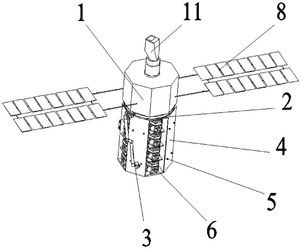
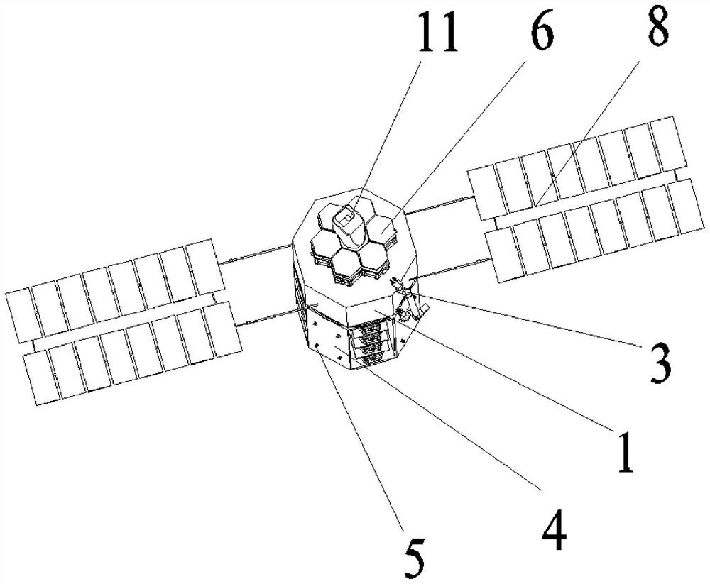
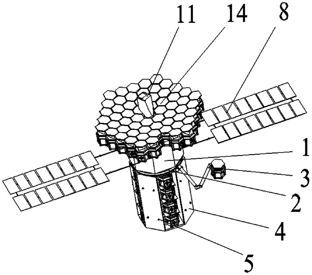
[0042] Specific implementation mode 1: refer to Figure 1 to Figure 5 This embodiment is described. This embodiment provides a method for a multi-space robot on-orbit collaboratively assembling a super-large space telescope. The method is implemented through the following steps:
[0043] Step 1: The large space telescope is divided into parts, and the telescope is divided into: the main mirror part, the secondary mirror part and the light blocking part, and the components of each part are loaded into a cargo compartment 4 respectively;
[0044] Step 2: The on-orbit assembly system consisting of the spacecraft platform 1 with the three-mirror module 11, the measuring ring 2, the retractable mechanical arm 3 and the cargo cabin 4 with the main mirror portion is launched to the predetermined working orbit of the telescope by the carrier rocket;
[0045] Step 3: splicing the parts in the cargo cabin 4 with the main mirror part one by one on the top of the spacecraft platform 1 thr...
specific Embodiment approach 2
[0053] Specific implementation two: refer to Figure 1 to Figure 5 This embodiment is described. This embodiment further defines the first step of the specific embodiment. In this embodiment, the outer wall of the cargo compartment 4 in the first step is uniformly distributed with a plurality of adapters 5 along the circumferential direction. A multifunctional robot 7 is also provided. The multifunctional robot 7 is locked on the outer wall of the cargo compartment 4 through a plurality of adapters 5. Other components and connection methods are the same as those in the first embodiment.
[0054] In this embodiment, the cargo compartment 4 is a cylindrical structure, and the cargo compartment 4 is provided with a modular sub-mirror discharge compartment, a secondary mirror module discharge compartment, a secondary mirror bracket discharge compartment, and a light blocking ring structure in sequence along the circumferential direction. The base material chamber and the light blo...
specific Embodiment approach 3
[0056] Specific implementation mode three: refer to Figure 1 to Figure 5 This embodiment is described. This embodiment further defines the steps 2 and 3 described in the specific embodiment 2. In this embodiment, in the second and third steps, the cargo cabin 4 with the main mirror is installed in the cargo compartment 4. The main mirror part is composed of several modular sub-mirrors 6 . Other compositions and connection methods are the same as those in the second embodiment.
[0057] In this embodiment, each modular sub-mirror 6 is provided with a mechanical locking and electrical connection interface.
PUM
 Abstract
Description
Claims
Application Information
 - R&D
- Intellectual Property
- Life Sciences
- Materials
- Tech Scout
- Unparalleled Data Quality
- Higher Quality Content
- 60% Fewer Hallucinations
Browse by: Latest US Patents, China's latest patents, Technical Efficacy Thesaurus, Application Domain, Technology Topic, Popular Technical Reports.
© 2025 PatSnap. All rights reserved.Legal|Privacy policy|Modern Slavery Act Transparency Statement|Sitemap|About US| Contact US: help@patsnap.com


