On-orbit assembly system of very large space telescope based on multi-space robot

A technology for space telescopes and assembly systems, applied in assembly machines, metal processing equipment, manufacturing tools, etc., can solve the problems of poor carrying and propulsion capabilities of launch vehicles, and the inability to meet the needs of ultra-large-caliber space optical loads.

Active Publication Date: 2022-04-12
HARBIN INST OF TECH
View PDF11 Cites 0 Cited by
  • Summary
  • Abstract
  • Description
  • Claims
  • Application Information

AI Technical Summary

Problems solved by technology

[0003] In order to solve the problem that the existing launch vehicle has poor loading and propulsion capabilities and cannot meet the requirements for carrying super-large-caliber space optical loads, the present invention further provides an on-orbit assembly system for super-large space telescopes based on multi-space robots;

Method used


Image

  • On-orbit assembly system of very large space telescope based on multi-space robot
  • On-orbit assembly system of very large space telescope based on multi-space robot
  • On-orbit assembly system of very large space telescope based on multi-space robot

Examples


specific Embodiment approach 1

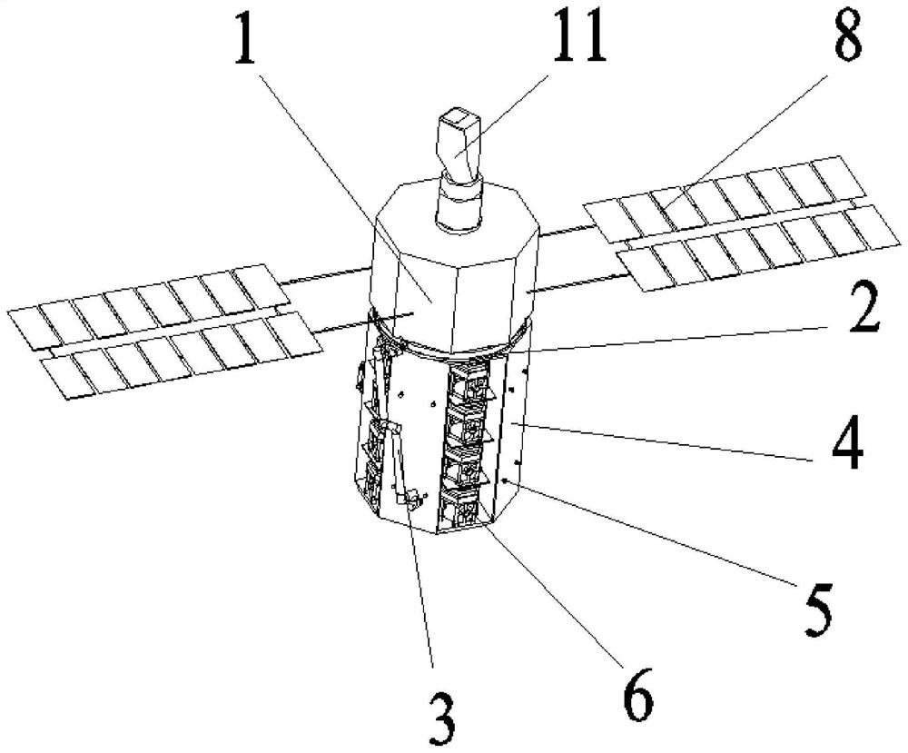
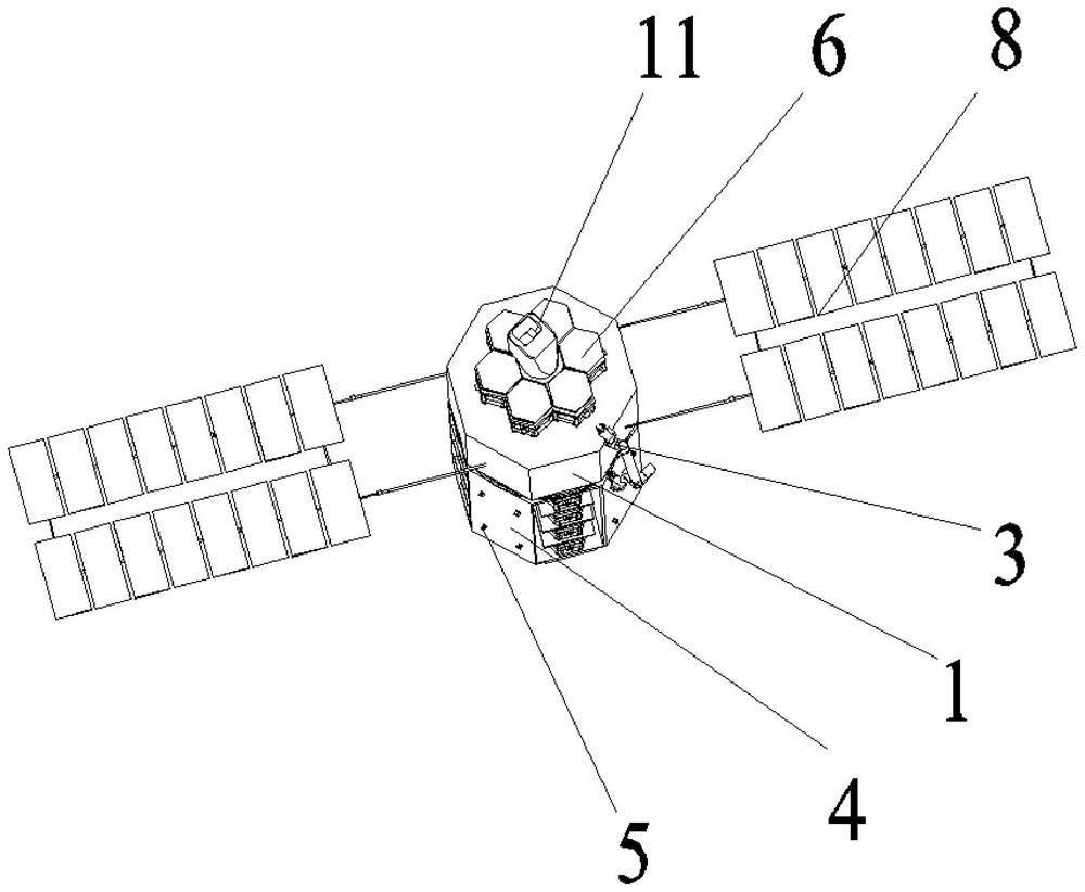
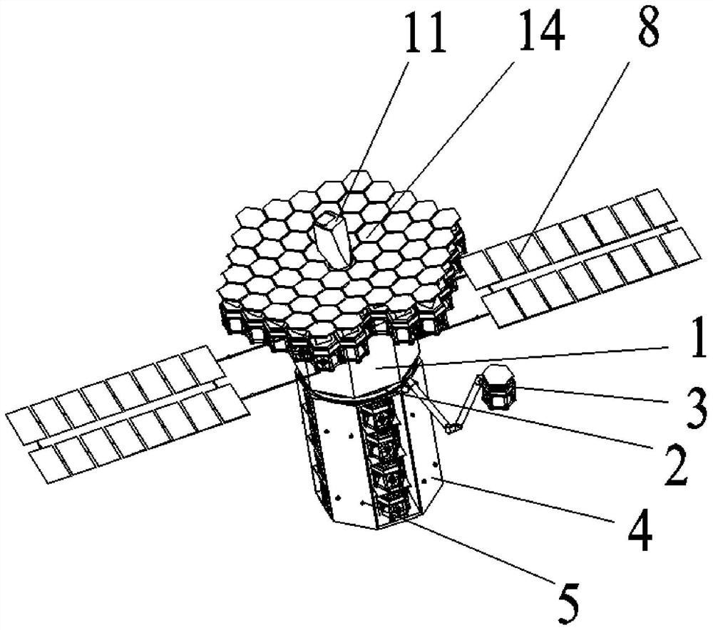
[0025] Specific implementation mode one: refer to Figure 1 to Figure 5 This embodiment is described. This embodiment provides an on-orbit assembly system for a very large space telescope based on a multi-space robot. The three-mirror module 11 and two solar wing sail panels 8, the three-mirror module 11 is positioned on the axis of the spacecraft platform 1, and the three-mirror module 11 is fixedly connected to the top of the spacecraft platform 1, and the two solar wing sail panels 8 Equidistantly installed on the outer circular surface of the spacecraft platform 1 along the circumferential direction, the metering ring 2 is arranged below the spacecraft platform 1, and one end of the metering ring 2 is fixedly connected to the bottom of the spacecraft platform 1, and the cargo compartment 4 is arranged on the The lower part of the metering ring 2, and the cargo compartment 4 is disassembled and connected with the metering ring 2, the telescopic robot arm 3 is arranged on th...

specific Embodiment approach 2

[0027] Specific implementation mode two: refer to Figure 1 to Figure 5 This embodiment is described. This embodiment is to further limit the telescopic robotic arm 3 described in the first specific embodiment. In this embodiment, the telescopic robotic arm 3 is connected to the sliding block through a ball joint. Other compositions and connection methods are the same as those in Embodiment 1.

[0028] In this embodiment, the telescopic mechanical arm 3 is slidingly connected to the metering ring 2 through a sliding block, so that the telescopic robotic arm 3 can perform a 360° circular rotation along the axis of the metering ring 2. The telescopic robotic arm 3 itself has 9 The degree of freedom includes 7 degrees of freedom of rotation of joints and 2 degrees of freedom of movement of arms. The telescopic manipulator 3 is hinged with the sliding block to realize that the telescopic manipulator 3 can swing relative to the metering ring 2 .

specific Embodiment approach 3

[0029] Specific implementation mode three: refer to Figure 1 to Figure 5 Describe this embodiment, this embodiment is to further limit the cargo compartment 4 described in the second specific embodiment, in this embodiment, the cargo compartment 4 is a cylindrical structure, and the cargo compartment 4 is sequentially provided with modular Sub-mirror discharge cabin, secondary mirror module discharge cabin, secondary mirror bracket discharge cabin, halo structure mounting base discharge cabin and halo structure discharge cabin, several modular sub-mirrors 6, secondary mirror modules 9, The three secondary mirror brackets 10, the light blocking ring structure 12 and the light blocking ring structure mounting base 13 are correspondingly placed in each discharge compartment. Other compositions and connection methods are the same as those in the second embodiment.

[0030] In such a setting, the original overall large-scale space telescope will be split into various parts, such ...


PUM


Abstract

The on-orbit assembly system for super-large space telescopes based on multi-space robots belongs to the technical field of spacecraft on-orbit services. The present invention solves the problem that existing launch vehicles have poor carrying and propulsion capabilities and cannot meet the requirements for carrying ultra-large-caliber space optical loads. , the three-mirror module in the assembly system of the present invention is located on the axis of the spacecraft platform, and the three-mirror module is fixedly connected to the top of the spacecraft platform, and the two solar wing sails are installed on the outer surface of the spacecraft platform at equal distances along the circumferential direction On the circular surface, the metering ring is set under the spacecraft platform, and one end of the metering ring is fixedly connected to the bottom of the spacecraft platform, the cargo cabin is set at the lower part of the metering ring, and the cargo cabin and the metering ring are disassembled and connected. On the metering ring, the telescopic robot arm is slidably connected to the metering ring through a sliding block, the telescopic robot arm can slide along the circumference of the metering ring, and the telescopic robot arm is used to grab parts in the cargo compartment.

Description

technical field [0001] The invention belongs to the technical field of on-orbit service of spacecraft, and in particular relates to an on-orbit assembly system of a super-large space telescope based on a multi-space robot. Background technique [0002] Space target surveillance, space situational awareness, and high-performance astronomical observation have strong demands for super-large-aperture optical payloads, and there is an urgent need to break through the development technology of super-large-aperture space optical payloads, laying a technical foundation for my country's development of the next generation of space surveillance and early warning systems and space astronomical telescopes . However, limited by the carrying and propulsion capabilities of launch vehicles, the existing launch vehicles cannot meet the carrying requirements of super-large-caliber space optical loads, which has led to bottlenecks in the development of the next-generation space surveillance and ...

Claims


Application Information

Patent Timeline
Patent Type & Authority Patents(China)
IPC IPC(8): B23P21/00
CPCB23P21/00
Inventor 孙永军蒋再男倪风雷赵京东刘宏
Owner HARBIN INST OF TECH
Why Eureka
Try Eureka