Radio visual entrance guard device

A wireless and access control technology, applied to interconnection devices, telephone communications, instruments, etc., can solve problems such as the inability to realize free control, and achieve the effect of convenient visualization and free control

Inactive Publication Date: 2007-07-18
CENT ACADEME OF SVA GROUP
View PDF0 Cites 14 Cited by
  • Summary
  • Abstract
  • Description
  • Claims
  • Application Information

AI Technical Summary

Problems solved by technology

[0002] At present, ordinary access control systems are fixedly connected through cables, and users can only use calling, intercom and other services within a fixed range, and cannot realize free control

Method used


Image

  • Radio visual entrance guard device

Examples


Embodiment approach

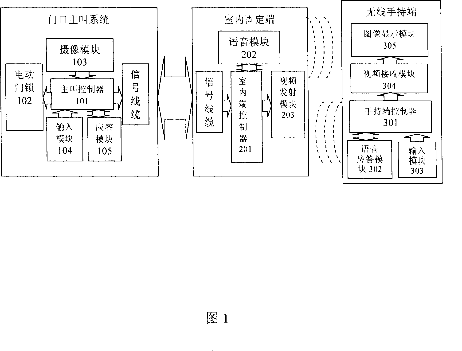
[0017] As shown in Figure 1, the present invention provides a wireless visual access control device, including a calling system at the door, a number of indoor fixed terminals connected to the calling system at the door with cables, and a number of indoor fixed terminals corresponding to each other. Wireless handheld terminal;

[0018] Wired signal transmission is performed between the calling system at the door and the indoor fixed terminal;

[0019] Wireless signal transmission is performed between the indoor fixed terminal and the wireless handheld terminal;

[0020] The calling system at the door includes a calling controller 101 and an electric door lock 102, a camera module 103, an input module 104 and an answering module 105 respectively circuit-connected to the calling controller 101;

[0021] In this embodiment, the calling controller 101 can use a 51-type single-chip microcomputer, the electric door lock 102 can use a general electromagnetic door lock, the camera mo...


PUM


Abstract

A radio visual entrance guard device is prepared as setting master calling unit at entrance, connecting said master calling unit to a numbers of indoor fixed ends by cable, setting a numbers of radio hand ends in corresponding to indoor fixed ends one by one, enabling to carry out cable signal transmission between entrance master calling unit and indoor fixed ends and to carry out radio signal transmission between indoor fixed end and radio hand ends.

Description

technical field [0001] The invention relates to a wireless visual door guard device. Background technique [0002] At present, ordinary access control systems are fixedly connected through cables, and users can only use services such as calling and intercom within a fixed range, and cannot realize free control. Contents of the invention [0003] A wireless visual access control device provided by the present invention overcomes the drawbacks of the existing access control technology that can only be fixedly connected, and can easily realize the visual and free control of the access control system at any place within the effective range, satisfying the Users' demand for wireless visual access control. [0004] In order to achieve the above purpose, the present invention provides a wireless visual access control device, which includes a calling system at the door, a number of indoor fixed terminals connected to the calling system at the door with cables, and a number of wir...

Claims


Application Information

Patent Timeline
Patent Type & Authority Applications(China)
IPC IPC(8): G07C9/00H04M1/725H04M9/00
Inventor 赵申苓
Owner CENT ACADEME OF SVA GROUP
Why Eureka
Try Eureka