
Backing roller core shaft

A backing and roll core technology, applied in the field of friction lubrication of rolling mills, can solve the problems of limited lubricating oil storage space, shutdown lubrication, unstable lubrication effect, etc., and achieve good lubrication effect and good lubrication effect.

Inactive Publication Date: 2007-07-25
郑红专 +1
View PDF0 Cites 3 Cited by
  • Summary
  • Abstract
  • Description
  • Claims
  • Application Information

AI Technical Summary

Problems solved by technology

[0005] The technical problem to be solved by the present invention is to overcome the shortcomings of the prior art such as limited lubricating oil storage space, frequent shutdown for lubrication, and unstable lubricating effect, and provide a backing roller mandrel with continuous lubrication and good lubricating effect

Method used


Image

  • Backing roller core shaft
  • Backing roller core shaft
  • Backing roller core shaft

Examples


Embodiment Construction

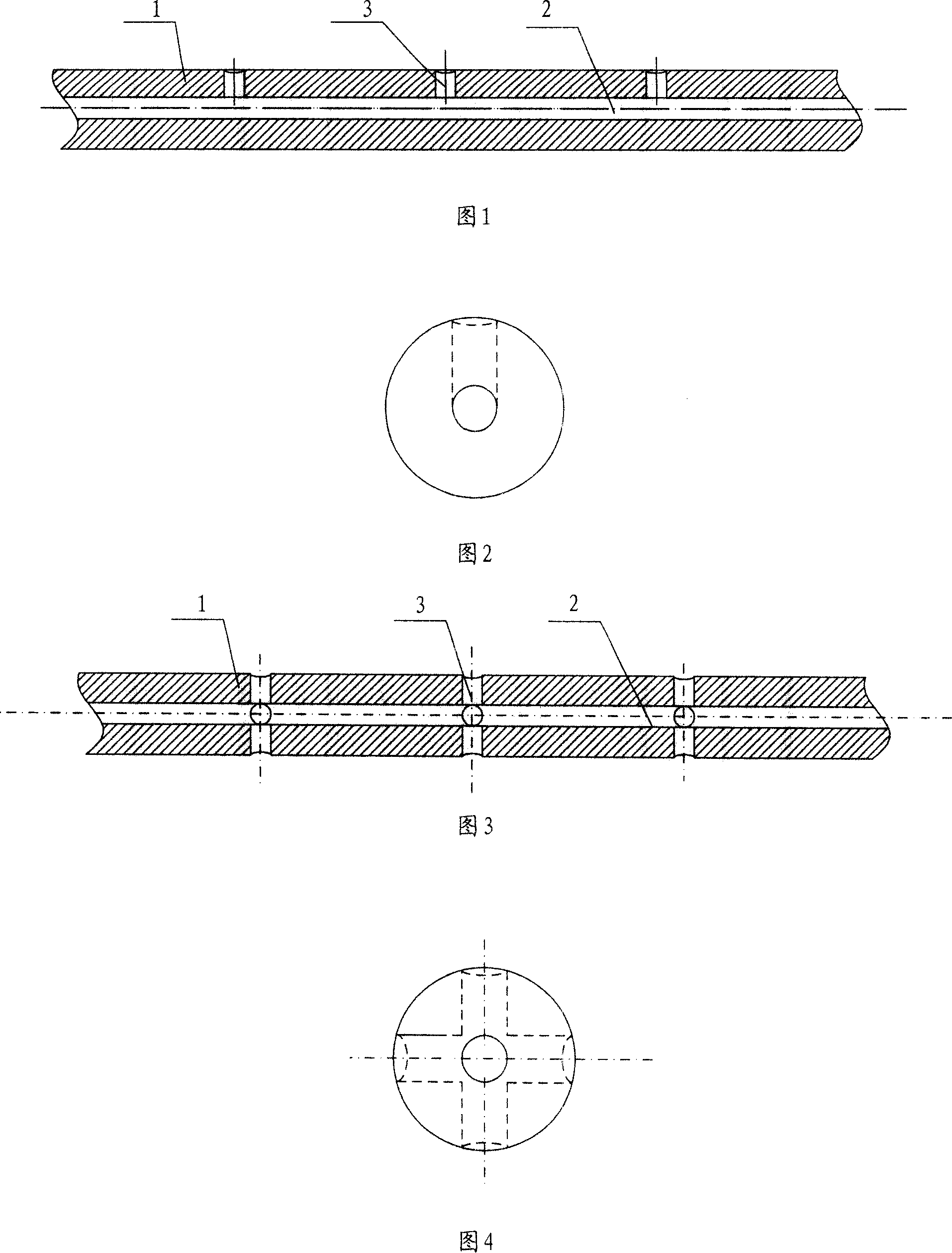
[0022] Please refer to Fig. 1 and Fig. 2. Fig. 1 is an axial sectional view of Embodiment 1 of the backing roller mandrel of the present invention, and Fig. 2 is a left view of Embodiment 1 of the backing roller mandrel of the present invention, combined with Fig. 1 and Fig. 2 The structure of the present invention can be understood more clearly. As shown in the figure, the mandrel of the backing roller includes a shaft body 1, and the shaft body 1 has a channel 2 in the axial direction for conveying lubricating oil. middle. The shaft body 1 is radially opened with an oil hole 3 , and the oil hole 3 penetrates through the channel 2 from the outer surface of the core shaft body 1 . The lubricating oil seeps out through the oil hole 3, and the backing roller bearing is installed at the position of the oil hole 3, the outer surface of the bearing is in contact with the middle support roller, and the inner surface of the bearing is in contact with the outer surface of the mandrel...


PUM


Abstract

A mandrel of baking roller for improving the lubrication effect has an axial lubricating oil channel with one or more radial oil releasing holes whose surficial ends are on the bottom of a ring slot.

Description

technical field [0001] The invention relates to the field of friction lubrication of rolling mills, in particular to a backing roll mandrel structure for improving the frictional lubrication efficiency of rolling mills. Background technique [0002] In the structure of the plate rolling mill, in order to improve the rigidity of the rolled steel plate and meet the processing requirements of different plates, the backing roll is often used to support the middle support roll, such as in the tower roll system, 12-roll mill, 20-roll In the rolling mill, the backing rolls are used to support the intermediate support rolls. The difference is that the former uses three backing rolls, and the latter uses four backing rolls. The backing rolls are in contact with the intermediate support rolls through bearings. When working, the pressure from the work roll is transmitted to the backing roll through the intermediate support roll, and the backing roll bears the load from the multi-roll m...

Claims


Application Information

Patent Timeline
Patent Type & Authority Applications(China)
IPC IPC(8): B21B29/00B21B28/00F16N1/00
Inventor 郑红专赵林珍
Owner 郑红专
Learn More