
Interface automatic forming method and interface automatic forming system

An automatic generation and interface technology, which is applied in the automatic interface generation system and the automatic generation of multi-parameter configuration interface of communication equipment, can solve the problem of interface generation without universality and scalability, and achieve good universality and scalability. Interface, overcome the effect of not being able to display large-capacity data

Active Publication Date: 2007-07-25
DATANG MOBILE COMM EQUIP CO LTD
View PDF0 Cites 70 Cited by
  • Summary
  • Abstract
  • Description
  • Claims
  • Application Information

AI Technical Summary

Problems solved by technology

[0010] The purpose of the present invention is to provide a method for automatic interface generation to solve the technical problem that the interface generation in the prior art does not have universality and scalability

Method used


Image

  • Interface automatic forming method and interface automatic forming system
  • Interface automatic forming method and interface automatic forming system
  • Interface automatic forming method and interface automatic forming system

Examples


Embodiment Construction

[0043] The present invention will be described in detail below in conjunction with the accompanying drawings.

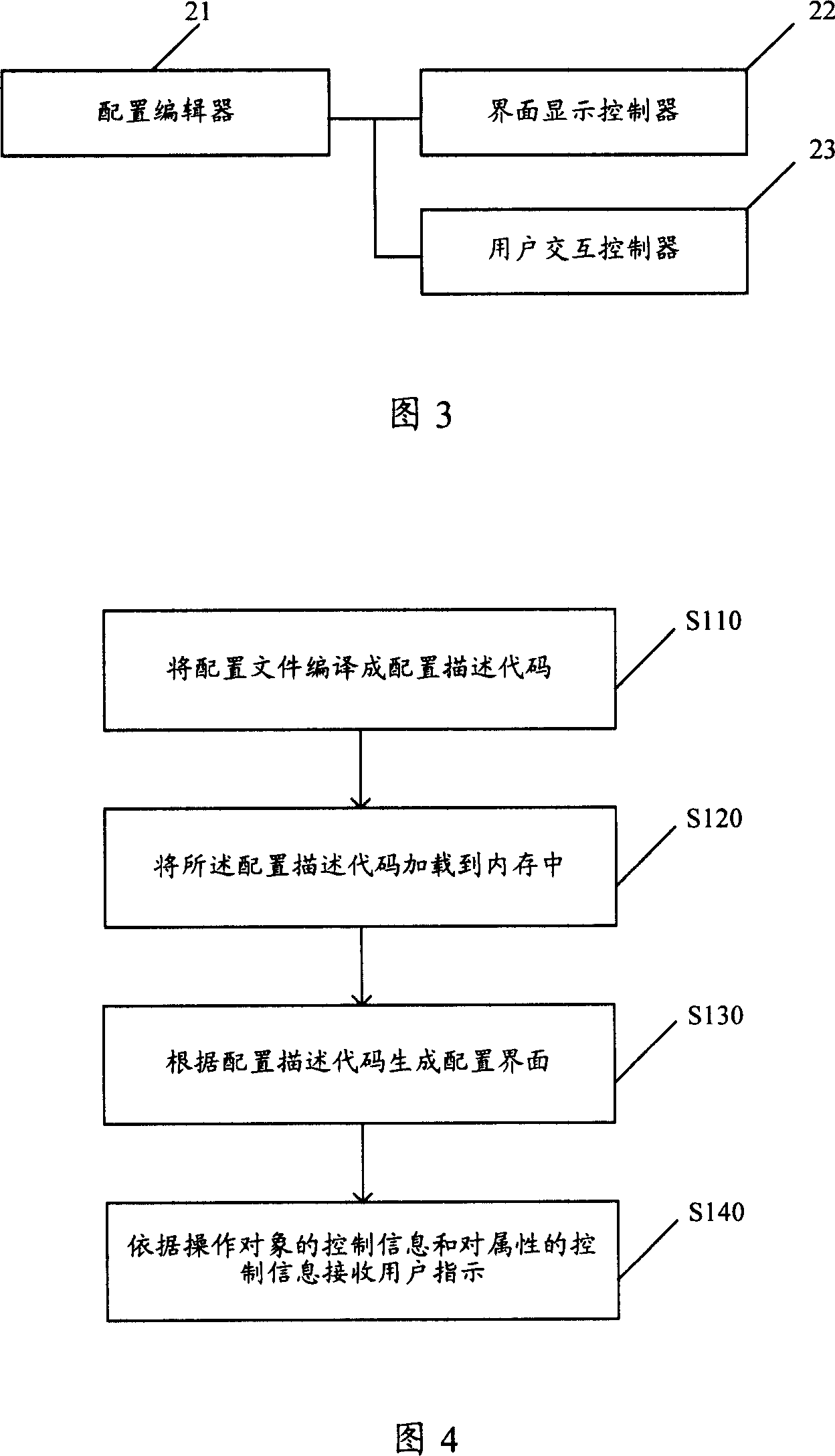
[0044] The invention discloses an interface automatic generation system. Please refer to FIG. 3 , which is a schematic structural diagram of the automatic interface generation system of the present invention. it includes:

[0045] Configuration editor 21: used to form a configuration file according to the information input by the user, and generate a configuration description code;

[0046] Interface display controller 22: configured to generate a configuration interface according to the configuration description code, the interface display controller at least includes a configuration object tree generating unit and an attribute list generating unit.

[0047] User interaction controller 23: receiving user instruction according to the control information of the operation object and the control information of the attribute.

[0048] The configuration editor 21 include...


PUM


Abstract

The method comprises: 1) compiling the configuration file into configuration description code; said configuration file comprises the operation-object structure information, operation-object control information, attribute information of each operation-object and the attribute-controlling information; 2) according to the configuration description code, generating the configuration interface: 21)according to said operation-object structure information, generating configuration object tree; 22)according to the attribute information of the operation-object, generating the attribute list of configuration objects; 3) according to the control information of the operation-object and the control information of the attribute-controlling information, receiving the user's instruction.

Description

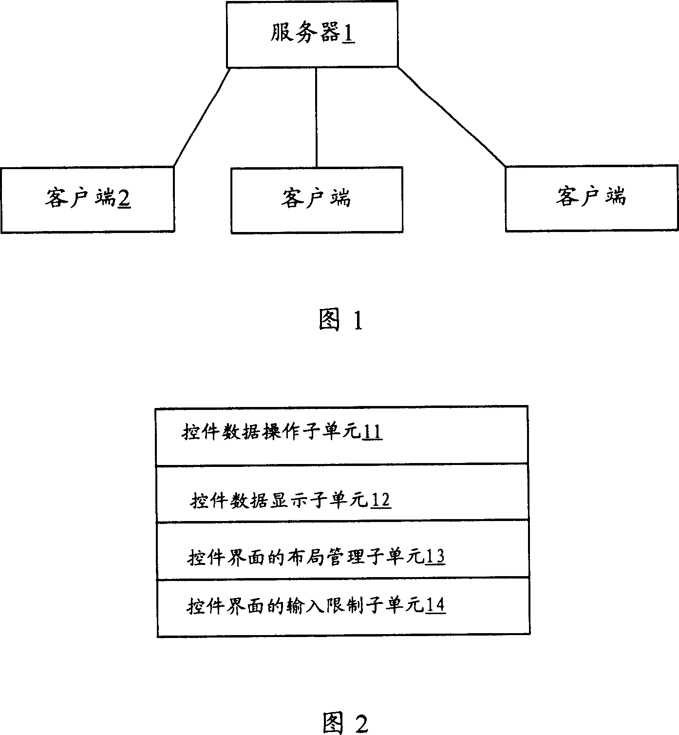
technical field [0001] The invention relates to an interface automatic generation technology, in particular to a method and an interface automatic generation system for multi-parameter configuration interfaces of communication equipment in the field of mobile communications. Background technique [0002] Please refer to FIG. 1 , which is a schematic structural diagram of a common distributed network in the prior art. It includes a server 1 and several clients 2. The server 1 is usually called the background, and the client 2 is called the foreground. The foreground can receive user instructions through an input interface, and transmit the received user instructions to the background, so that the background can control its work. Since many clients 2 require different instructions for user input, technicians set different input interfaces for different clients for users to input information. Moreover, even if it is the same client 2, when a certain operation object of the cl...

Claims


Application Information

Patent Timeline
Patent Type & Authority Applications(China)
IPC IPC(8): H04Q7/34G06F3/048G06F9/44G06F3/0481
Inventor 王一唯张海波王安辉
Owner DATANG MOBILE COMM EQUIP CO LTD
Learn More