Polishing machine

A polishing machine and rotor technology, applied in the polishing machine field, can solve the problems of reducing air throughput, high pressure loss, high cost, etc., and achieve the effect of avoiding the deposition of grinding powder

Active Publication Date: 2007-07-25
WUXI BUHLER MASCH MFG CO LTD
View PDF3 Cites 0 Cited by
  • Summary
  • Abstract
  • Description
  • Claims
  • Application Information

AI Technical Summary

Problems solved by technology

[0005] Hollow shafts with multiple openings are expensive to produce, while small opening cross-sectio

Method used


Image

  • Polishing machine
  • Polishing machine
  • Polishing machine

Examples


Embodiment Construction

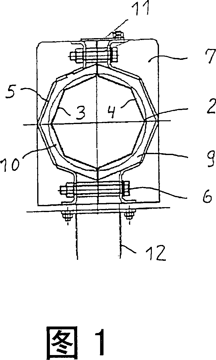
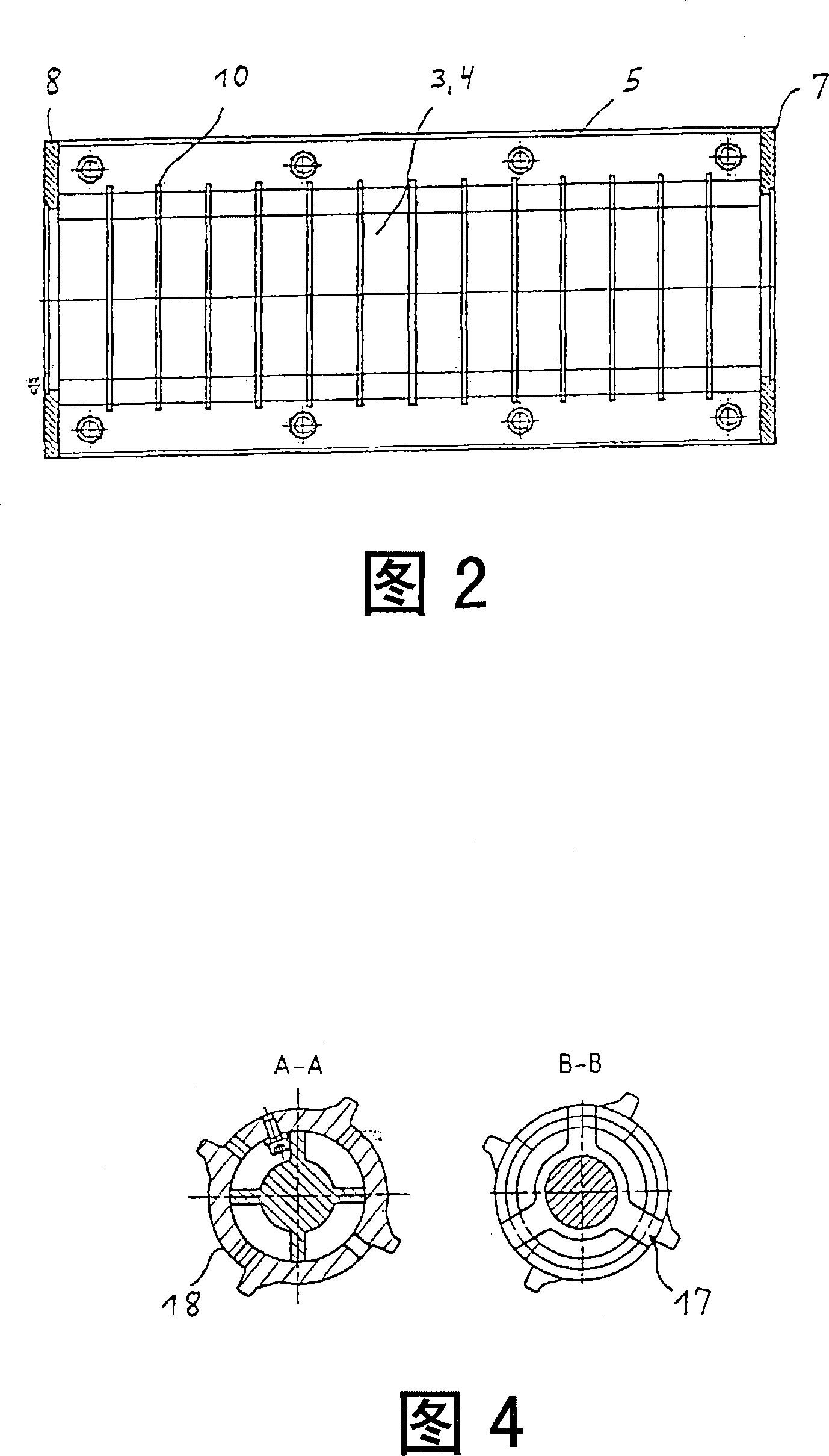
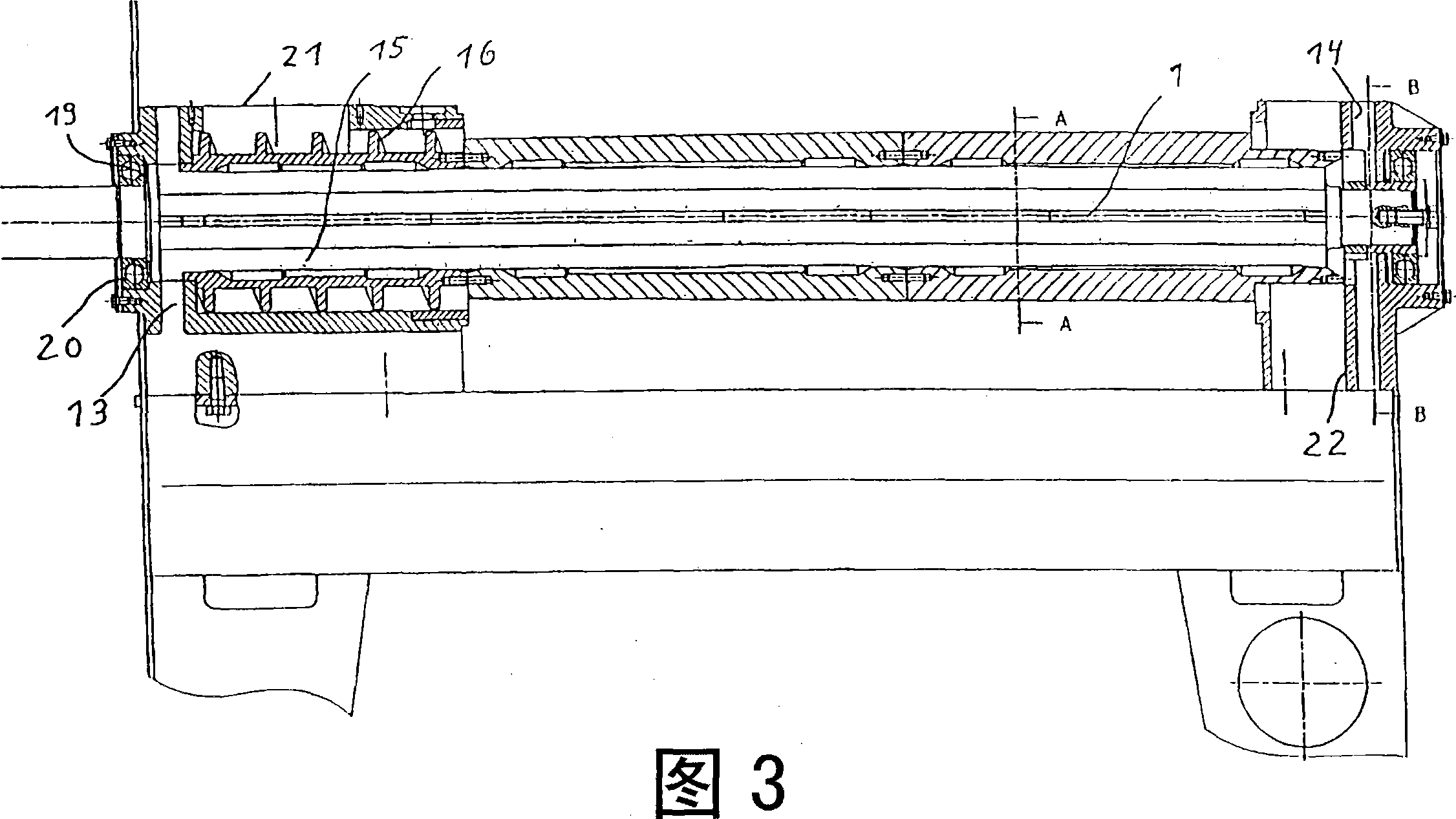
[0017] The polishing machine shown here with only the parts considered here has a cylindrical rotor 1 equipped with conventional grinding tools 18 , eg cams. In the region where the polishing tool is located, the rotor 1 is enclosed by an octagonal screen 2 comprising two screen plates 3 and 4 . The screen 2 is in turn enclosed by a two-part perforated basket 5 in the form of a sheet jacket comprising two half-shells. The screen plates 3, 4 and the perforated basket 5 are connected to the self-supporting unit by threaded connections 6 and retaining sleeves, which are sealed at the surface with the end plates 7, 8 . A uniform narrow gap 9 is located between the sieve 2 and the perforated basket, thus creating a uniform and high air velocity which allows only a slight tendency for the ground powder to settle.

[0018] The half-shells of the perforated basket 5 have short, inwardly projecting ribs 10, which are advantageously provided with plug-in protrusions. The half-shells o...


PUM


Abstract

The invention relates to a polishing machine for rice or other cereals, comprising a perforated basket (5) that is embodied in a simplified manner. Said perforated basket (5) is provided with two curved walls in the form of half-shells with ribs (10) that protrude towards the interior. Preferably, both half-shells are connected to a split sieve (2) by means of screws and spacing elements so as to form a supporting perforated basket (5).

Description

technical field [0001] The present invention relates to polishers, and in particular to polishers or grinders for polishing or grinding paddy, even wheat, and the like. Background technique [0002] Polishers or grinders for rice or other grains with grinding or polishing rotors arranged horizontally or vertically are known in the art. For example, patent publications EP-A-699478 or EP-A-646414 disclose machines with vertically arranged rotors housing grinding or polishing tools. The rotor and tool are spaced apart and enclosed by a screen which in turn is housed in a perforated basket. The perforated basket is enclosed by a housing so that the grinding or polishing product cannot escape freely. The housing can be a full sleeve, or have an opening for a viewing window. Furthermore, the rotor can be configured as a hollow shaft with smaller openings in the area where the tool is located, to supply air and / or moist air and / or water into the treatment area. In a similar man...

Claims


Application Information

Patent Timeline
IPC IPC(8): B02B3/04
CPCB02B3/00B02B3/04
Inventor 弗兰克-奥托·格利茨
Owner WUXI BUHLER MASCH MFG CO LTD
Why Eureka
Try Eureka