Wireless network system
一种无线网络系统、无线信号的技术,应用在无线网络系统领域,能够解决信号品质下降等问题,达到减少干涉、防止利用带宽的降低的效果
- Summary
- Abstract
- Description
- Claims
- Application Information
AI Technical Summary
Problems solved by technology
Method used
Image

Examples
no. 1 Embodiment approach
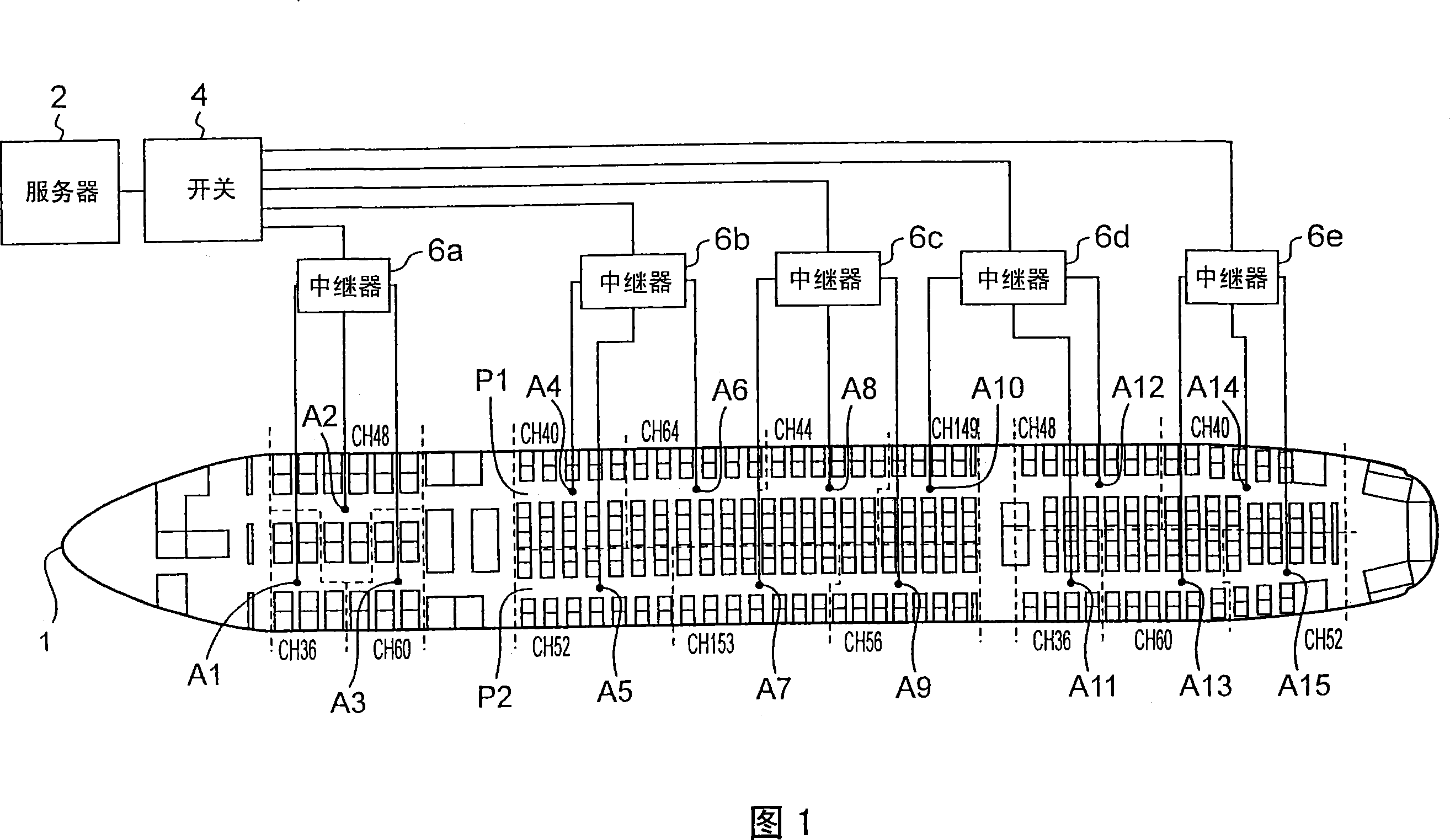
A5
CH52
A10
CH149
A15
CH52
Here, the channel used is a frequency based on the wireless LAN standard stipulated by IEEE802.11a, and is a frequency available in the United States. FIG. 5 shows a table showing frequencies and center frequencies of wireless LAN standards stipulated by IEEE802.11a.
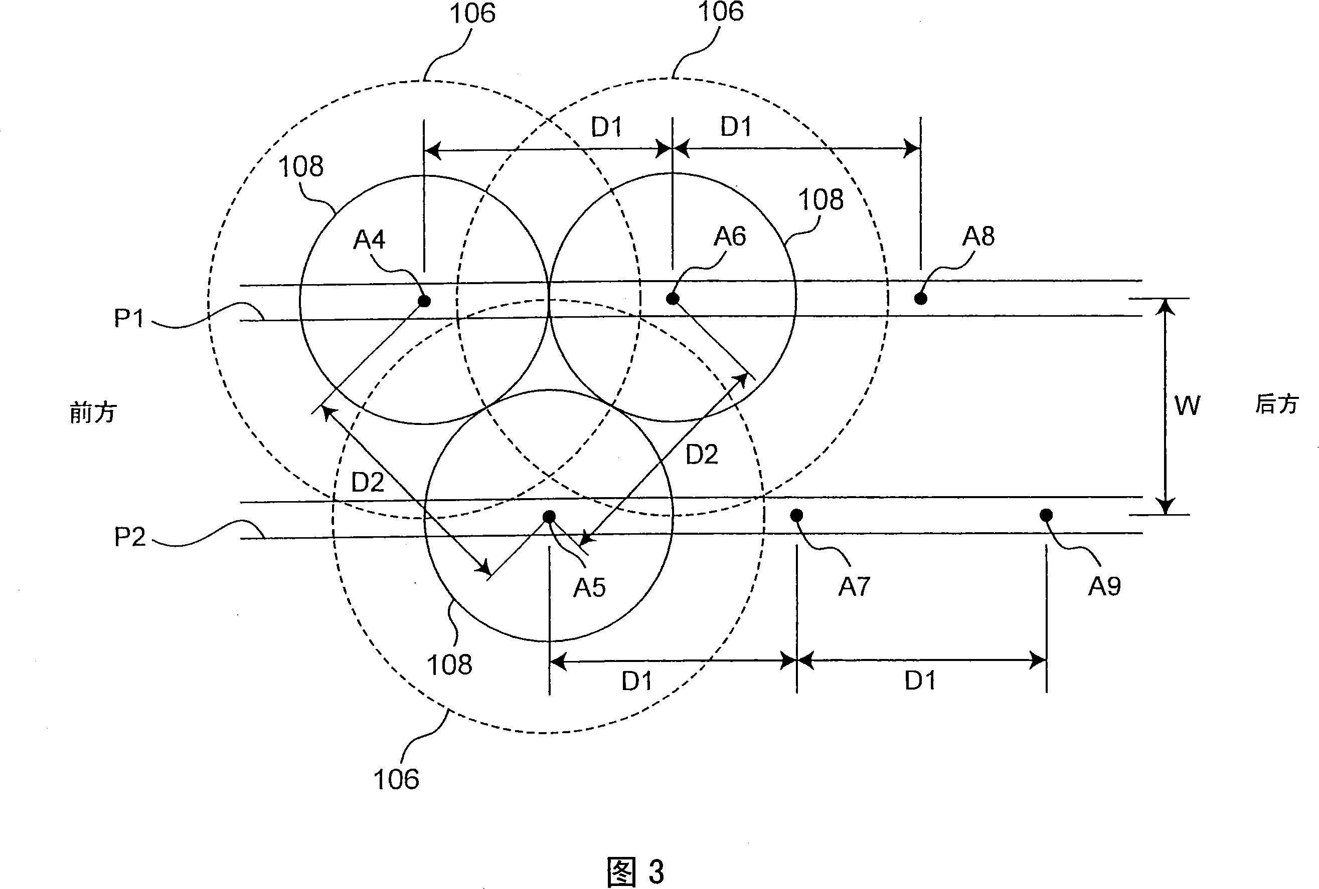
When multiple access points are used, the channels used are close to each other, which often causes interference and reduces the utilization of bandwidth. Whether interference is caused depends on the conditions of both the closeness of the channels and the distance between the access points, not just one of them. Even if the same channel is used, if the distance between the access points is large enough, or the effective ranges described later do not overlap, there will be no interference. Conversely, if the distance between access points is extremely short, it is difficult to prevent the interference of radio waves from multiple access points even if ...
no. 2 Embodiment approach
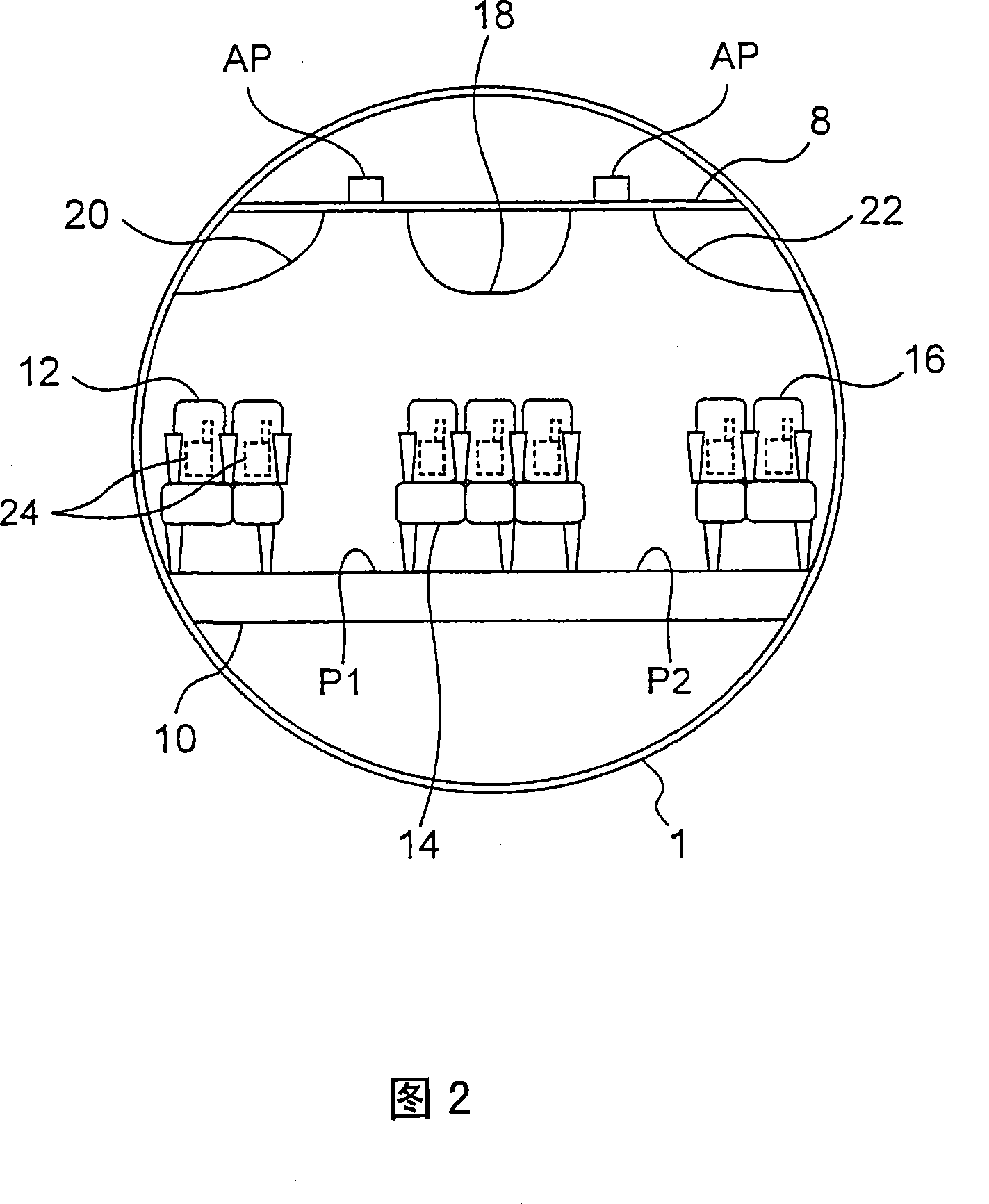
Fig. 4 is a configuration diagram of a second embodiment of the present invention.
[0030]
In the first embodiment shown in FIG. 2 , all access points are installed on the ceiling 8 . On the other hand, in the second embodiment shown in FIG. 4 , the access points arranged along one passage such as the passage P2 are provided on the floor 10 such as the rear side thereof. The access points arranged along another channel P1 are set on the ceiling 8 . If this relationship is described using FIG. 3, then the access points A4, A6, A8 arranged along the channel P1 are set on the ceiling 8, and the access points A5, A7, A9 arranged along the channel P2 are set on the ceiling 8. Floor 10 in.
[0031]
After installing the access points as shown in FIG. 4 , compared with when all the access points are installed on the ceiling 8 or all on the floor 10 , when the access points are arranged as shown in the second embodiment, the access points can be lengthened. The distance between ...
no. 3 Embodiment approach
Fig. 6 is a configuration diagram of a third embodiment of the present invention.
The access point shown in the first embodiment uses a non-directional access point for transmitting radio waves. On the other hand, in the third embodiment, directional access points are used. For example: for access point A4, use an access point with lateral directivity across the channel P1 and channel P2. The same applies to other access points. The range of communication partner seats received by each of the access points A1 to A15 is indicated by a dotted line. This range is horizontally longer than the range shown in FIG. 1 . In this way, even if the intensity of the transmitted radio waves is increased, there is an effect of reducing the interference of radio waves in the longitudinal direction (the direction in which the channel extends).
As a modified example of FIG. 6 , the directivity of the radio waves output by the access point may be directed toward the channel. In this way, i...
PUM
 Abstract
Description
Claims
Application Information
 - R&D
- Intellectual Property
- Life Sciences
- Materials
- Tech Scout
- Unparalleled Data Quality
- Higher Quality Content
- 60% Fewer Hallucinations
Browse by: Latest US Patents, China's latest patents, Technical Efficacy Thesaurus, Application Domain, Technology Topic, Popular Technical Reports.
© 2025 PatSnap. All rights reserved.Legal|Privacy policy|Modern Slavery Act Transparency Statement|Sitemap|About US| Contact US: help@patsnap.com