Lighting system

A lighting system and lighting beam technology, applied in the field of lighting systems, can solve problems such as damage, bulky projection device, overheating, etc., and achieve the effects of reducing the probability of damage, improving collection efficiency, and increasing intensity

Inactive Publication Date: 2007-08-01
AIXIN TECH
View PDF0 Cites 5 Cited by
  • Summary
  • Abstract
  • Description
  • Claims
  • Application Information

AI Technical Summary

Problems solved by technology

[0004] In the dual-lamp lighting system 100, since the parallel light beams 112a, 122a directly illuminate the second and first lamps 120, 110 respectively, and repeatedly pass through the wicks 112, 122, it is easy to cause the wicks 112, 122 to overheat and be damaged.
In addition, the parallel light beams 112a, 122a formed by the parabolic lampshades 114, 124 will gradually diverge, and because the parallel light beams 112a, 122a have a long optical path, the light beam collection efficiency is poor, and thus the dual-lamp lighting system 100 is reduced. The intensity of the illumination beam provided
In addition, the double-lamp lighting system 100 uses the first lamp 110 and the second lamp 120 to be arranged oppositely, and the reflector 130 is arranged between the first lamp 110 and the second lamp 120 to combine the light beams, so a larger space is required for With such a structure, the volume of the projection device is relatively large. Under the current trend of pursuing short, small, light and thin electronic products, the dual-lamp lighting system 100 with this structure obviously cannot meet the current design requirements.

Method used


Image

  • Lighting system
  • Lighting system
  • Lighting system

Examples


no. 1 approach

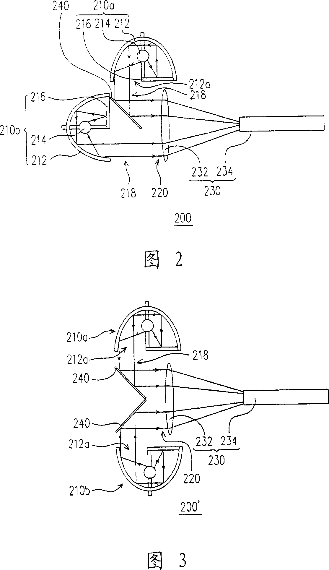
[0051]Referring to FIG. 2, the lighting system 200 of this embodiment includes two first lamps 210a and 210b and a second reflective element 240, wherein the second reflective element 240 is arranged between the first lamps 210a and 210b, and each The first lamps 210 a and 210 b include a first lampshade 212 , a first wick 214 and a first reflective element 216 , and the axes of the first wicks 214 of the two first lamps 210 a and 210 b are arranged to be perpendicular to each other. The first lampshade 212 has a first light emitting section 212a, and the first reflective element 216 is connected to the first lampshade 212 and partially shields the first light emitting section 212a. The first wick 214 is adapted to provide the first divergent light, and the first lampshade 212 and the first reflective element 216 are adapted to form the first divergent light into a first parallel beam 218, and the first parallel beam 218 has never been illuminated by the first reflective elemen...

no. 2 approach

[0063] Please refer to FIG. 6 , the lighting system 200c of the present embodiment is similar to the lighting system 200 of the first embodiment, so the same reference numerals will be used to denote the same components in FIG. 6 . The lighting system 200c of this embodiment includes two lamps 210c, 210d and a reflective element 240' disposed between the two lamps 210c, 210d. Wherein, each lamp 210c, 210d includes a lampshade 212', a wick 214' and a shading element 217. The lampshade 212' has a light emitting section 212a', and the wick 214' is disposed in the lampshade 212', and the light shielding element 217 covers part of the wick 214'. The wick 214' is adapted to provide divergent light, and the lampshade 212' is adapted to form the divergent light into a parallel beam 218', and the parallel beam 218' is output from a part of the light output section 212a'. In addition, the reflective element 240' is located in front of the light emitting section 212a' of one of the lamp...


PUM


Abstract

A lighting system for supply parallel light beams comprises two first lamps while each one comprises a first lamp cover, a first corn, and a first reflector. The first lamp cover has the first outlet section. The first reflector is connected with the first lamp cover and shades part of the first outlet section. The first corn provides the first radiate light. The first lamp cover and the first reflector can form the first radiate light into the first parallel beam to be output from the non-shaded first outlet section. The invention also comprises at least one second reflector between two lamps and part arranged on the path of first parallel beam, to combine the first parallel beams into parallel light beam. The invention uses reflector and / or shade element to adsorb the ultraviolet light and infrared light to reduce the temperature of corn.

Description

technical field [0001] The invention relates to an illumination system, in particular to an illumination system with multiple lamps. Background technique [0002] Please refer to FIG. 1 , the existing dual-lamp lighting system 100 includes a first lamp 110 , a second lamp 120 , and a reflector 130 . Wherein, the first lamp 110 is opposite to the second lamp 120 , and the reflector 130 is disposed between the first lamp 110 and the second lamp 120 . The reflector 130 has two reflecting surfaces 132 , 134 , and the included angles between them and the axis 50 are respectively 45 degrees. [0003] As noted above, the first and second light fixtures 110, 120 include wicks 112, 122 and parabolic shades 114, 124, respectively. The wicks 112, 122 are adapted to provide divergent light, they are located on the same axis 50, and the parabolic lampshades 114, 124 are used to form the divergent light into parallel beams 112a, 122a, and the optical axes of the two parallel beams 112a,...

Claims


Application Information

Patent Timeline
Patent Type & Authority Applications(China)
IPC IPC(8): F21S2/00F21V3/00F21V7/04F21V13/04F21V13/12F21K9/23F21K9/237
Inventor 郑权得
Owner AIXIN TECH
Why Eureka
Try Eureka