X-ray ct apparatus and x-ray ct fluoroscopic apparatus

A technology of X-ray and equipment, applied in the field of X-ray CT image reconstruction method and X-ray CT equipment, which can solve the problems such as difficulty in radiation exposure

Inactive Publication Date: 2007-08-08
GE MEDICAL SYST GLOBAL TECH CO LLC
View PDF0 Cites 30 Cited by
  • Summary
  • Abstract
  • Description
  • Claims
  • Application Information

AI Technical Summary

Problems solved by technology

As a result, it is difficult to reduce radiation exposure in such a way that only the region of interest is irradiated with X-rays
Moreover, there is no channel direction collimator that can be moved in such a channel direction that only the region of interest is irradiated with X-rays

Method used


Image

  • X-ray ct apparatus and x-ray ct fluoroscopic apparatus
  • X-ray ct apparatus and x-ray ct fluoroscopic apparatus
  • X-ray ct apparatus and x-ray ct fluoroscopic apparatus

Examples


Embodiment 3

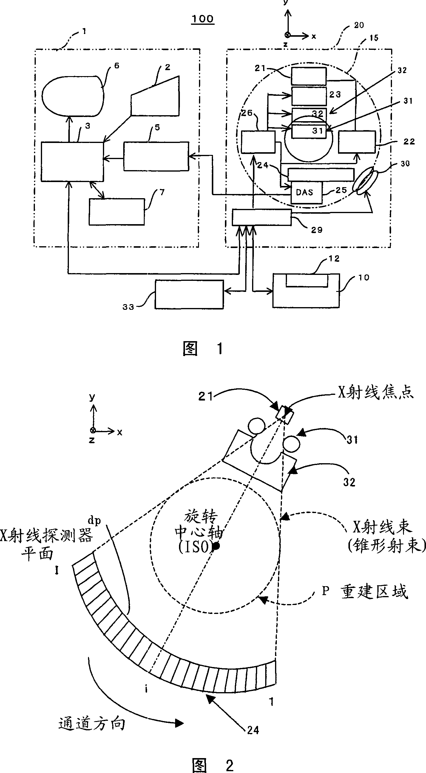
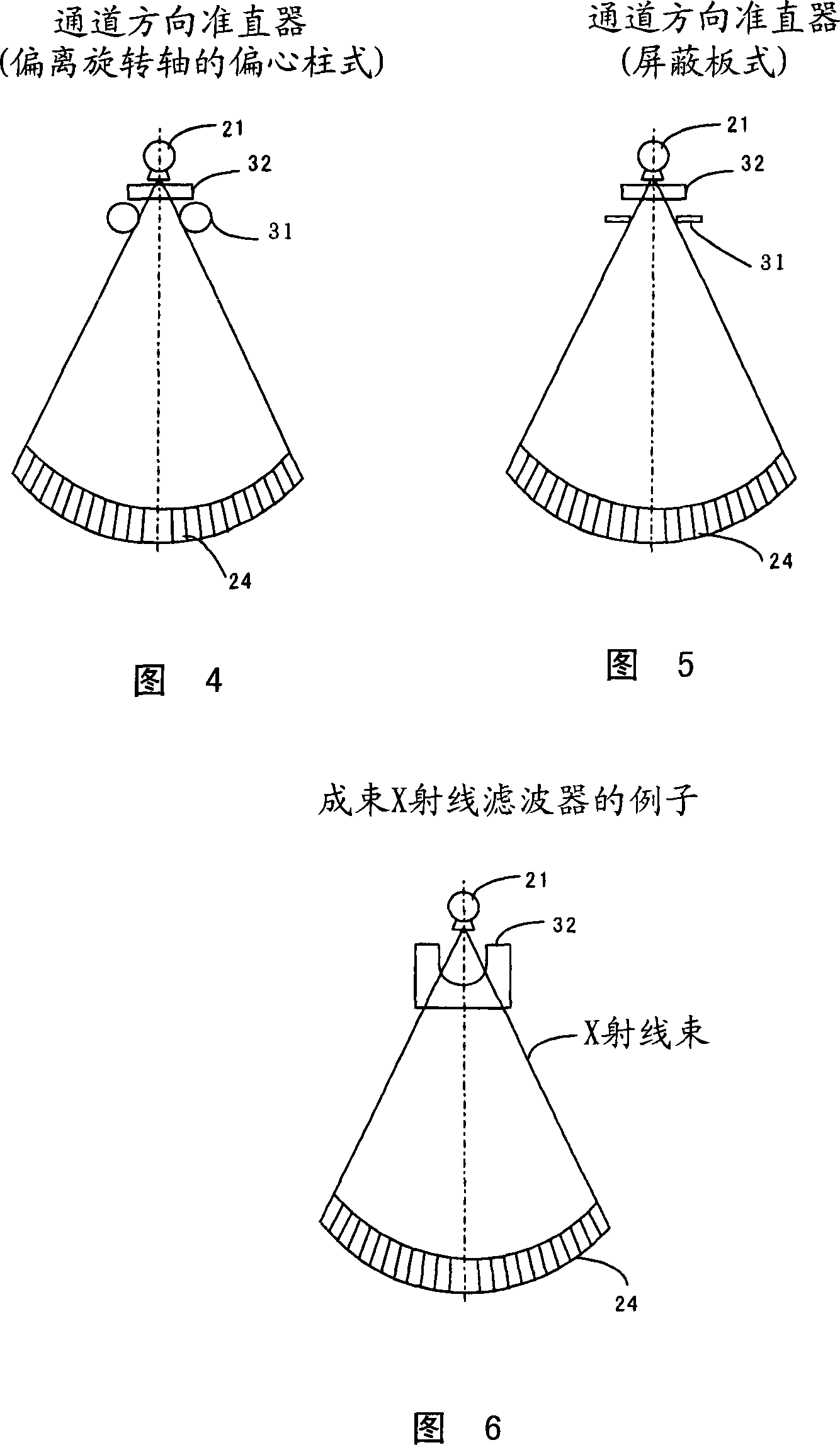
[0114] Considering that for the collimator of Embodiment 3, a shielded cylindrical shape (eccentric cylindrical collimator that deviates from the rotation axis) (Figure 4) or a shielded plate shape (plate collimator) (Figure 5) can be conceived for the collimator of embodiment 3, so according to the present invention, this Both collimators are suitable. When DAS25 reads the z-channel data to complete the collimator control in the z-direction (slice thickness direction), execute the collimator control in the channel direction by the following, that is, find out in advance the X-ray detection that will be incident on multiple lines The position of the X-ray on the detector 25 is determined by the angle β (observation angle β) of the X-ray data acquisition line and the position and size of the region of interest to be imaged, and is based on the aperture of the collimator in the direction of the channel. Position and aperture width are feed forward control. Moreover, the value of the...

Embodiment 4

[0270] Although Embodiment 3 is described with reference to the channel direction X-ray collimator 31, the use of the beam-forming X-ray filter 32 as shown in FIG. 31 can produce similar effects.

[0271] FIG. 31 shows the normal position of the beamed X-ray filter, that is, when the amount of movement in the channel direction is zero.

[0272] Fig. 32 and Fig. 33 show examples in which the movement amounts of the beam-forming X-ray filter are Δd1 and Δd2, respectively. In this case, the control can be completed so that the straight line connecting the center of the region of interest and the X-ray focal point overlaps the X-ray propagation path of the beamed X-ray filter 32 constituting the shortest straight line.

[0273] In order to achieve their overlap:

[0274] Mathematical expression 19

[0275] γ mean =(γ max +γ min ) / 2

[0276] For the distance from the X-ray focal point to the beam forming filter indicated by D as shown in FIG. 31, the following holds.

[0277] Δdi=D·tan...

Embodiment 5

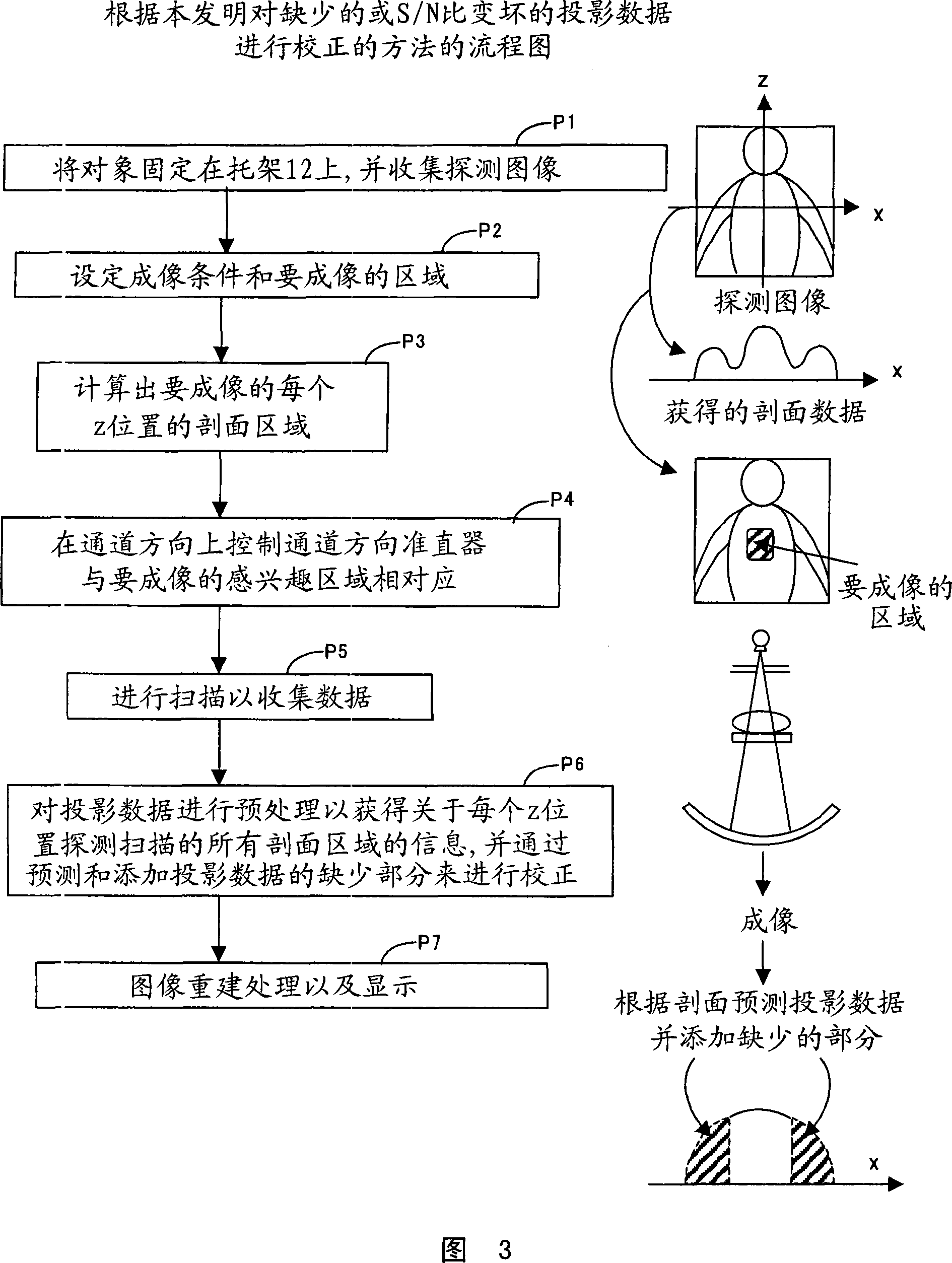
[0280] An example in which the present invention is applied to an X-ray CT fluoroscopy apparatus is shown in FIG. 34. First, in step S1, the entire X-ray tomographic image is imaged.

[0281] Next, in step S2, a region of interest to be imaged is set on the X-ray tomographic image imaged in step S1. When setting the region of interest, the operator in the scanning room equipped with the gantry 20 sets the region of interest by using the X-ray CT fluoroscopy operation panel 33 provided at hand.

[0282] Then in step S3, the channel direction collimator 31 or the shape X-ray collimator 32 irradiates the region of interest or its center in the channel direction with X-rays during tracking to collect projection data in the region of interest.

[0283] Then in step S4, as shown in FIG. 3, correction of the projection data is performed based on the entire cross-sectional area, and image reconstruction is performed on the corrected projection data.

[0284] Then in step S5, it is checked...


PUM


Abstract

Tomography or X-ray CT fluoroscopy reduced in exposure to radiation in an X-ray CT apparatus or an X-ray CT fluoroscopic apparatus is to be substantialized. A channel-direction X-ray collimator or a beam forming X-ray filter is positionally controlled in the channel direction to carry out X-ray data acquisition while irradiation with X-rays limited to only the region of interest. Either the profile area of the whole subject is obtained or the profile area of the whole subject is predicted from views or scout images of irradiation of the whole subject out of X-ray projection data. Image reconstruction of views not irradiating the whole subject out of the collected X-ray projection data is carried out by predicting lacking parts from the profile area of the whole subject and making corrections accordingly. It is thereby made possible to irradiate only the region of interest with X-rays to reduce the exposure of the subject of tomography by the X-ray CT apparatus to X-rays or the exposure the subject to X-rays and the exposure of the operator's hands to radiation at the time of puncturing in X-ray CT fluoroscopy.

Description

Technical field [0001] The present invention relates to an X-ray CT (computed tomography) imaging method and X-ray CT equipment, as well as to a projection data used for projection data lacking a part of the channel or containing material (such as metal) that is difficult to propagate X-rays X-ray CT image reconstruction method and X-ray CT equipment. The present invention relates to an X-ray CT image reconstruction method and X-ray CT apparatus for projection data to be collected in a channel direction by a collimator, thereby enabling low radiation exposure. [0002] The present invention relates to an X-ray CT fluoroscopy image reconstruction method and an X-ray CT fluoroscopy device for reducing the exposure of X-rays to an operator's hand. Background technique [0003] There is an increasing demand for reducing the dose of radiation received by patients in X-ray CT. In order to achieve low exposure, the low exposure technology is established to try to achieve a significant r...

Claims


Application Information

Patent Timeline
Patent Type & Authority Applications(China)
IPC IPC(8): A61B6/03H05G1/30
CPCA61B6/4085A61B6/027A61B6/032A61B6/03G01T1/00
Inventor 西出明彦河内直幸泉原彰乡野诚渡边诚记
Owner GE MEDICAL SYST GLOBAL TECH CO LLC
Why Eureka
Try Eureka