Connection unit for connecting an electronic device to an optical data bus

A technology for connecting units and electronic equipment, applied in the direction of optical components, optical, electrical components, etc., can solve the problems of complex installation, multi-space, high cost, etc., and achieve the effect of improving mechanical stability

Inactive Publication Date: 2007-08-08
CONTINENTAL AUTOMOTIVE GMBH
View PDF1 Cites 2 Cited by
  • Summary
  • Abstract
  • Description
  • Claims
  • Application Information

AI Technical Summary

Problems solved by technology

[0004] Known connection units require relatively much space inside the electronic device
In addition, it is complex and costly to install

Method used


Image

  • Connection unit for connecting an electronic device to an optical data bus
  • Connection unit for connecting an electronic device to an optical data bus

Examples


Embodiment Construction

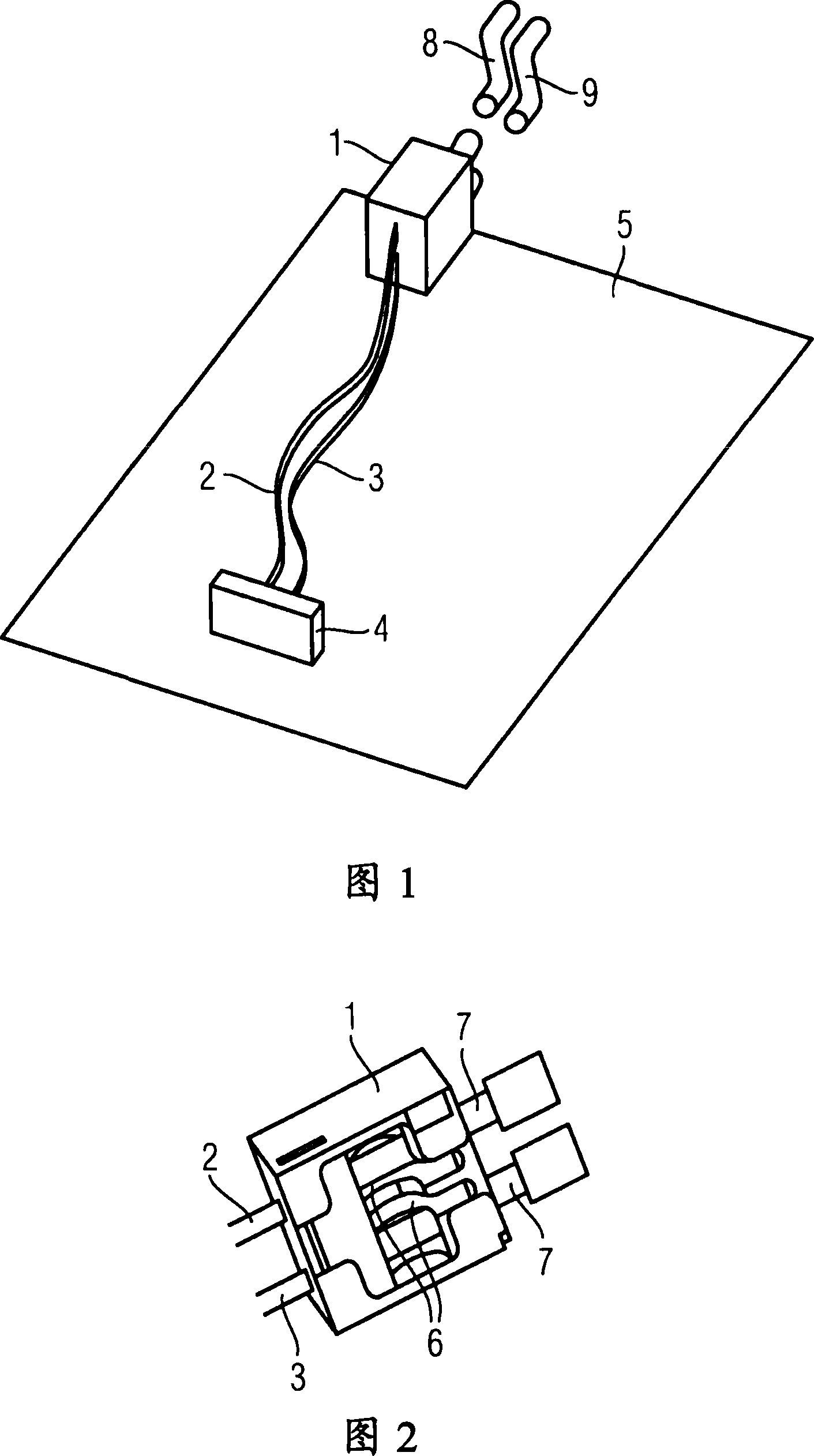
[0019] FIG. 1 shows the structural concept of a known connection unit, which is installed, for example, in an existing motor vehicle for connecting electronic devices to two bus optical waveguides 8 and 9 belonging to the MOST bus. Here, the optical waveguides 8 and 9 are only shown schematically and partially.

[0020] The connection unit consists of a plug housing 1 , two device optical waveguides 2 and 3 and a conversion unit 4 . The conversion unit 4 includes: a receiver, which is connected with the device optical waveguide 2, and is used to convert the optical signal from the MOST bus into an electrical signal; and a transmitter, which is connected with the device optical waveguide 3, and converts the electrical signal into an electrical signal to be Optical signal sent to the MOST bus. When another optical data bus is used, only one device optical waveguide in duplex mode can be used instead of two single device optical waveguides in simplex mode.

[0021] Both the plu...


PUM


Abstract

The invention relates to a connection unit (10) for connecting an electronic device to at least one bus fibre-optic (19) of an optical data bus, said unit comprising a plug housing (11), at least one device fibre-optic (12), which comprises a first (13) and a second (14) light transmission surface, the first light transmission surface (13) being located in the plug housing (11), a mechanical compensation unit (16), which is located in the plug housing (11) and which guarantees sufficient optical contact between the first light transmission surface (13) of the device fibre-optic and a light transmission surface (20) of the bus fibre-optic (19), in addition to a conversion unit (15) that is connected to the second light transmission surface (14) of the device fibre-optic (12) and that converts optical signals into electric signals and/or electric signals into optical signals. According to the invention, the second light transmission surface (14) of the device fibre-optic (12) and the conversion unit (15) are located in the plug housing (11) and the conversion unit (15) is connected to an electric transmission line (17).

Description

technical field [0001] The invention relates to a connection unit for connecting an electronic device to at least one bus waveguide of an optical data bus, the connection unit having: a plug housing; at least one device lightguide, the device lightguide having a first and The second optical transmission surface, wherein the first optical transmission surface is arranged inside the plug housing; the mechanical adjustment unit arranged inside the plug housing is used to ensure the optical transmission between the first optical transmission surface of the device optical waveguide and the bus optical waveguide sufficient optical contact between the surfaces; and a conversion unit connected to the second optical transmission surface of the optical waveguide of the device for converting optical signals into electrical signals and / or converting electrical signals into optical signals. Background technique [0002] Such connection units are installed in existing motor vehicles to fa...

Claims


Application Information

Patent Timeline
Patent Type & Authority Applications(China)
IPC IPC(8): H04B10/00H04B10/80
CPCG02B6/3897H04B10/801
Inventor 托马斯・内格尔
Owner CONTINENTAL AUTOMOTIVE GMBH
Why Eureka
Try Eureka