Deflection-degree-decreasing rolling mill

A deflection, rolling mill technology, applied in the direction of metal rolling stand, metal rolling mill stand, metal rolling, etc., to achieve the effect of reducing deflection deformation, reducing deflection, and reducing lateral thickness difference

Inactive Publication Date: 2007-08-15
郑红专 +1
View PDF0 Cites 1 Cited by
  • Summary
  • Abstract
  • Description
  • Claims
  • Application Information

AI Technical Summary

Problems solved by technology

[0007] The technical problem to be solved by the present invention is to provide a new type of cold rolling mill for controlling the two-dimensional deflection in view of the problem of two-dimensional deflection of the roll in the prior art. The deflection deformation in the vertical direction is small, and the deflection deformation in the horizontal direction can also be reduced, so that the deflection deformation produced by the roll is greatly reduced, thus reducing the lateral thickness difference of the rolled piece and improving the quality of the rolled piece. Dimensional accuracy

Method used


Image

  • Deflection-degree-decreasing rolling mill
  • Deflection-degree-decreasing rolling mill
  • Deflection-degree-decreasing rolling mill

Examples


Embodiment 1

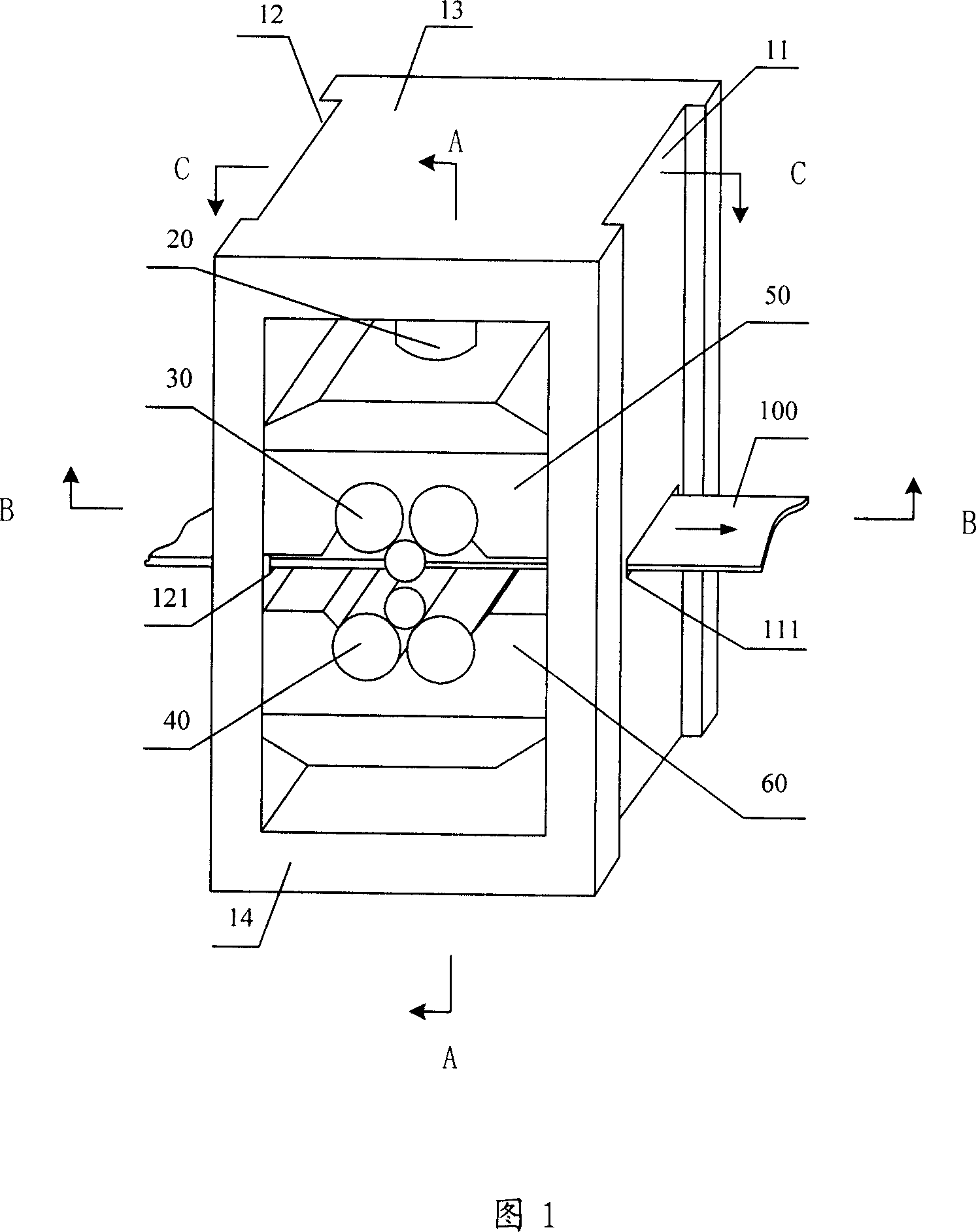
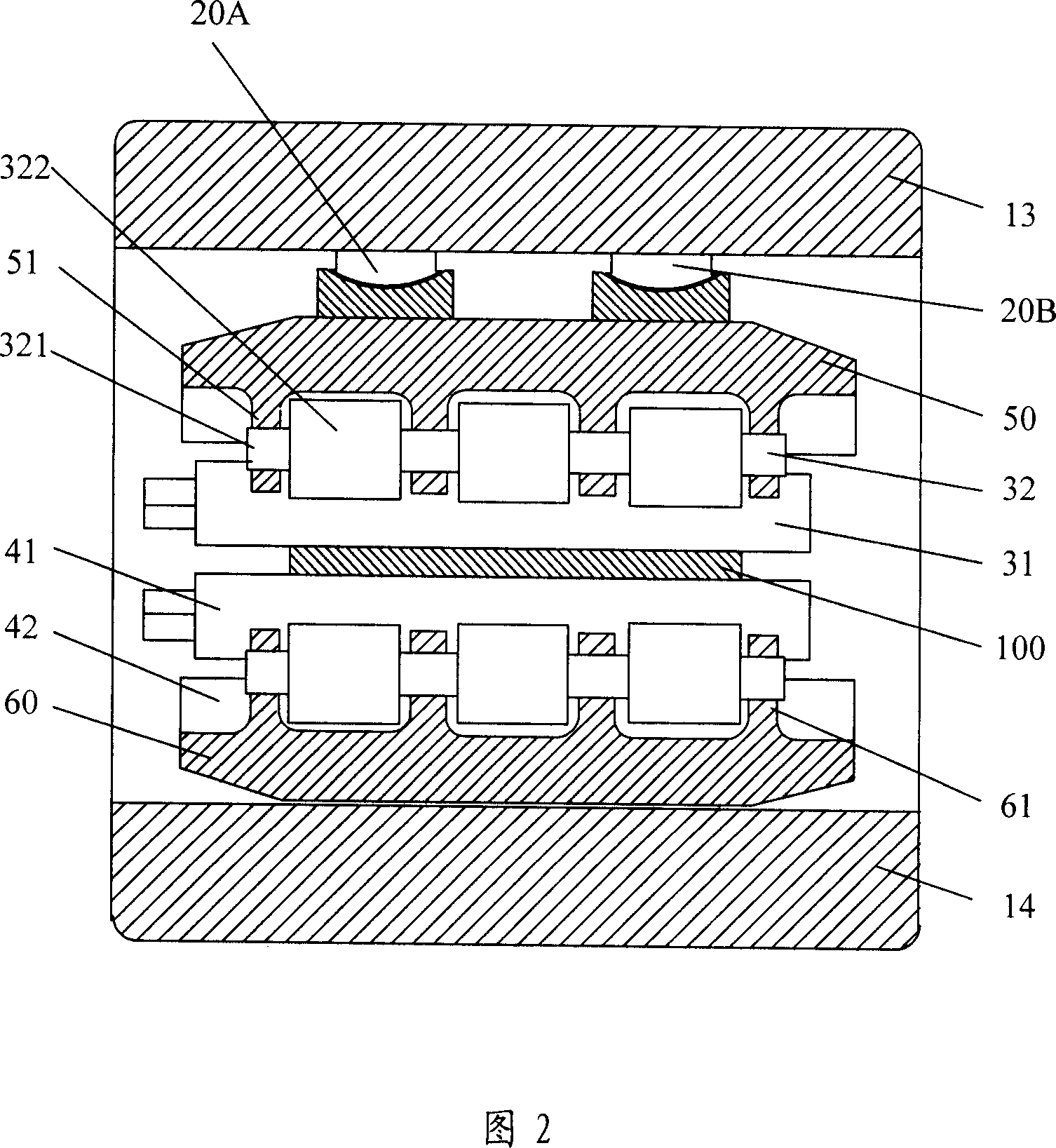
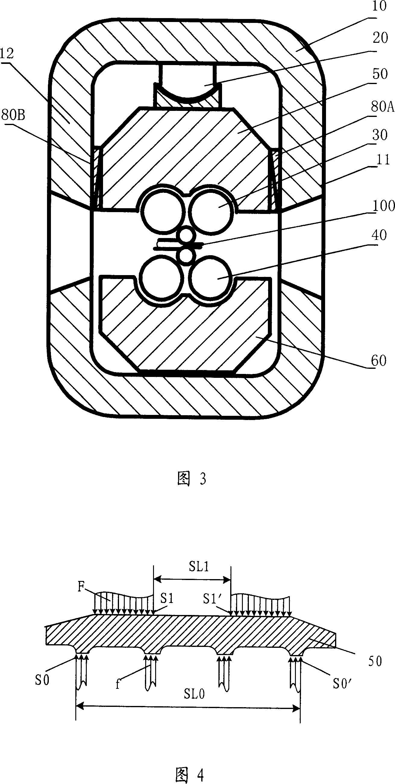
[0048] Fig. 1 is a schematic perspective view of the first embodiment of the present invention, Fig. 2 is a side sectional view of the A-A section of Fig. 1 , and Fig. 3 is a side sectional view of the C-C section of Fig. 1 . As shown in Fig. 1, Fig. 2 and Fig. 3, the present embodiment is a six-high rolling mill, and the main structure includes a frame 10, and the frame 10 is equipped with an upper roll stand 50 and a lower roll stand 60, and the upper roll stand 50 and the lower roll stand The roll stand 60 is connected to the upper tower-shaped roll system 30 and the lower tower-shaped roll system 40 respectively in the form of multi-point support beams, and also includes a pressing device 20 and a horizontal support device 80 . The frame 10 is a whole frame surrounded by a panel 11 , a back panel 12 , a top panel 13 and a bottom panel 14 . The surface of the back plate 12 is provided with a material inlet 121 for the rolled piece 100 to enter, and the surface of the panel ...

Embodiment 2

[0062] This embodiment is based on the embodiment 1, adding some additional components to further improve the precision of the rolled piece.

[0063] A vertical support device 70 for supporting the vertical rolling force is also arranged horizontally between the lower roll stand 60 and the frame bottom plate 14. The vertical support device 70 can be pads of different sizes and specifications, and the thickness forms a series. Pad blocks are used to realize the adjustment of the rolling line, and the vertical supporting device 70 may also adopt a hydraulic device or an electric pressurizing device. There can be one or more vertical support devices 70 .

[0064] FIG. 8 is a schematic diagram of the force on the lower roll stand when a vertical support device is provided. As shown in FIG. 8 , a vertical support device 70 is centrally set between the lower roll stand 60 and the bottom plate 14 . During the transmission process of the above-mentioned rolling force, the lower suppo...

Embodiment 3

[0075] Fig. 13 is a schematic structural view of the third embodiment of the present invention, which is a twelve-high rolling mill. This embodiment is structurally different from the above embodiment in that the upper tower roll system also includes several upper intermediate rolls arranged between an upper work roll and a plurality of upper backup rolls, and the lower tower roll system also includes Several lower intermediate rolls are arranged between a lower work roll and a plurality of lower backup rolls.


PUM


Abstract

The invention relates to a roller for reducing flexural degree, comprising a frame which contains an upper roller base and a lower roller base via multipoint support beams respectively connected with an upper roller system and a lower roller system in tower structure. The frame is formed by a panel, a back plate, a top plate and a bottom plate, wherein the back plate and the panel are disposed with a material inlet and an outlet, the top plate and the upper roller base are symmetry arranged with two presses which is pressed on the upper roller base via a safe concave along the axle of the upper roller system, the minimum distance between two nearest function points of two presses on the upper roller base is smaller than the distance between two furthest function points of upper roller system on the upper roller base. The invention can reduce flexural degree and reduce deformation.

Description

technical field [0001] The invention relates to a cold rolling mill for producing plates and strips, especially to reduce the deflection in the two-dimensional direction of the rolls, which can make the rolled plates and strips have high lateral thickness accuracy characteristics and reduce deflection degree of rolling mill. Background technique [0002] In the production of plate and strip, the thickness accuracy and flatness of the plate are important indicators to reflect the quality of the product. The thickness automatic control technology has been developed to a very high level in recent years, but the flatness control technology has been under research, and there are still various types of rolling mills in the existing technology when rolling strips with large width-to-thickness ratios. Serious lateral thickness difference problem. The transverse thickness difference of the plate and strip depends on the size and shape of the work roll gap, and one of the main reaso...

Claims


Application Information

Patent Timeline
Patent Type & Authority Applications(China)
IPC IPC(8): B21B31/02B21B31/16B21B29/00B21B13/02B21B13/14B21B1/22
Inventor 郑红专赵林珍
Owner 郑红专
Why Eureka
Try Eureka