Bionic machinery chelonian with two-stage freedom degree flipper mechanism
A degree of freedom, flipper technology, applied in directions such as non-rotating propulsion elements, to facilitate disassembly, improve reliability, and improve angular velocity and rotation range
- Summary
- Abstract
- Description
- Claims
- Application Information
AI Technical Summary
Problems solved by technology
Method used
Image

Examples
Embodiment Construction
[0021] The present invention will be described in detail below in conjunction with the accompanying drawings and embodiments.
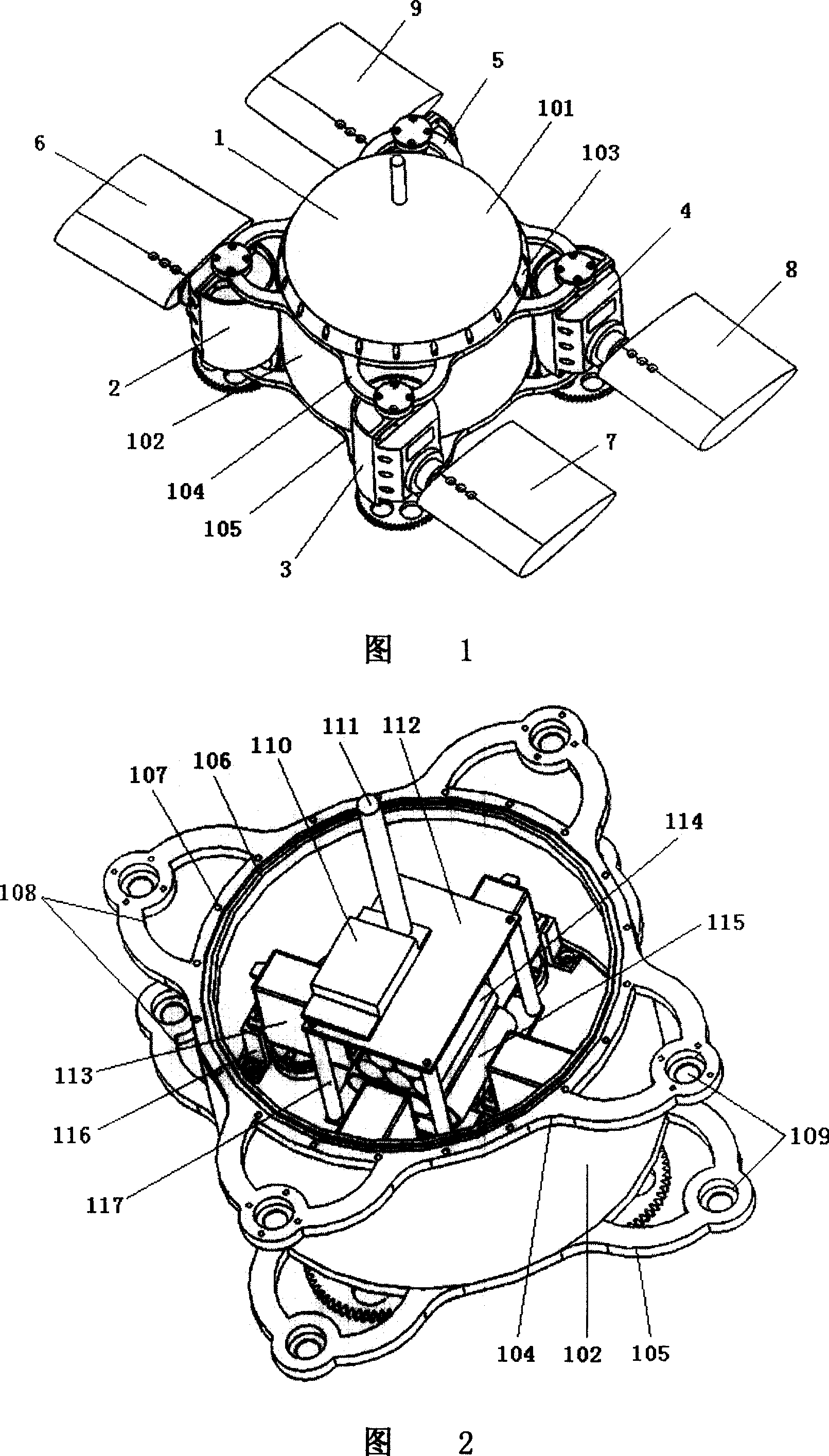
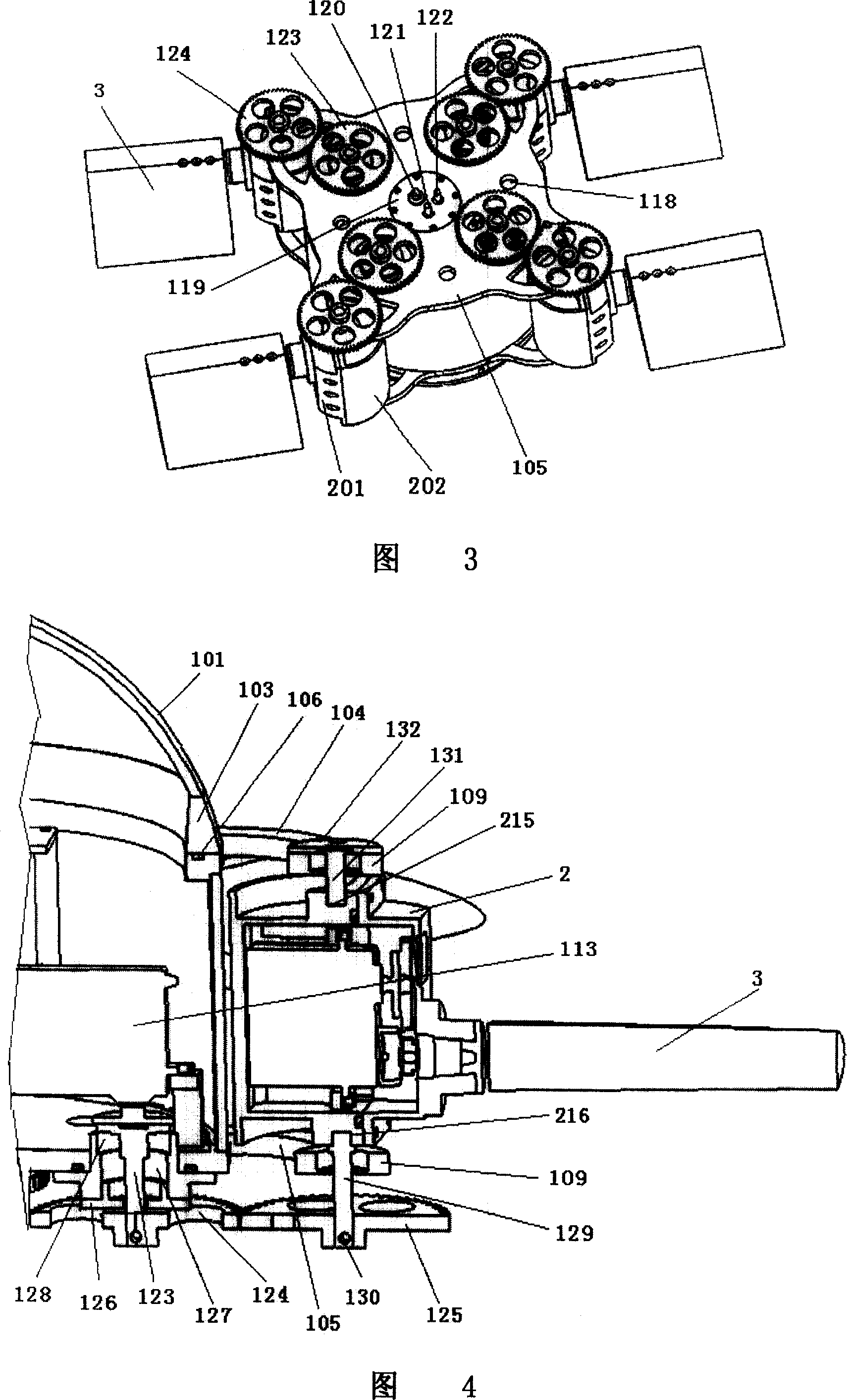
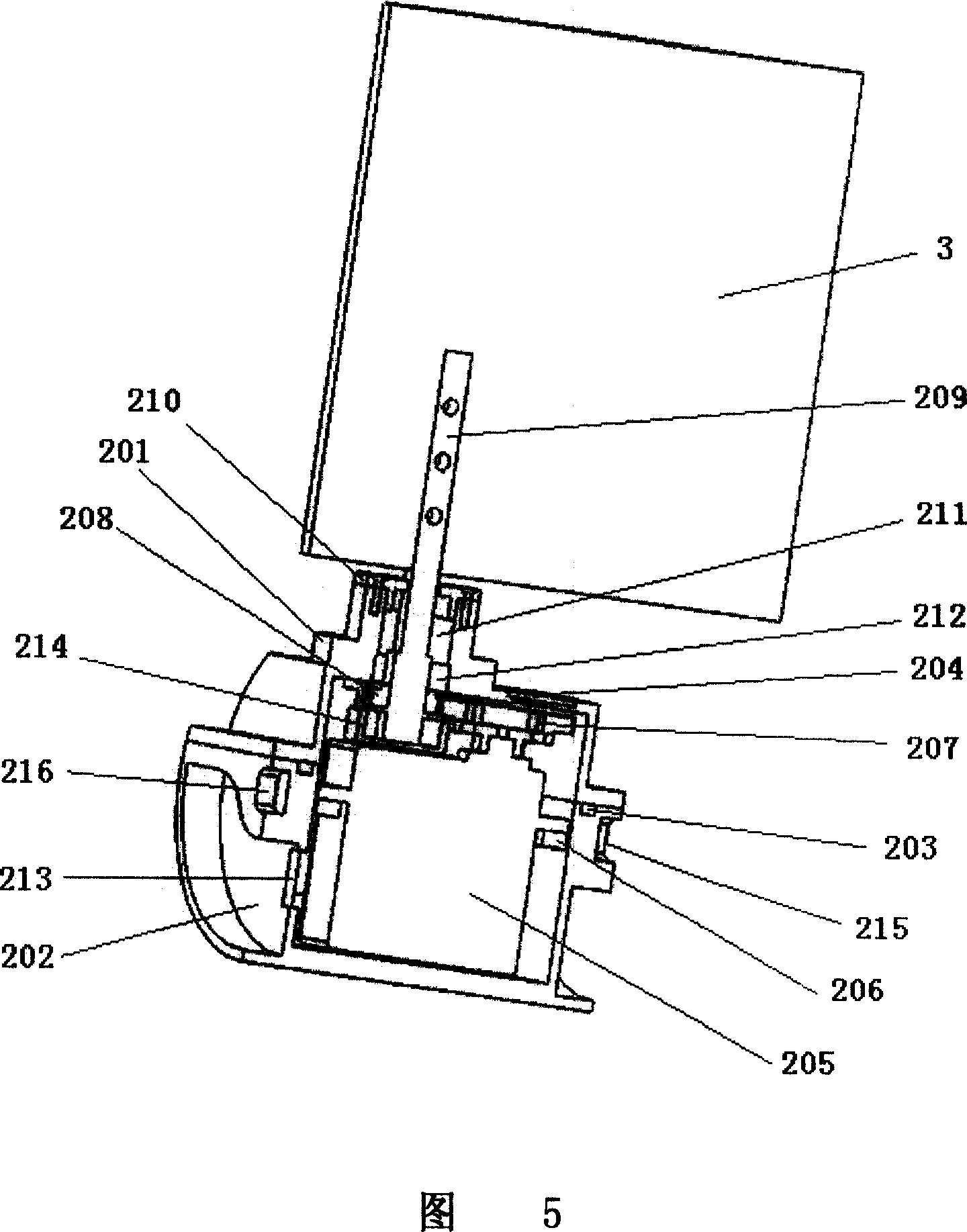
[0022] As shown in Fig. 1, the present invention comprises a robot turtle main cabin module 1, swings and is connected to the main cabin module 1 circumferential direction, four flipper drive modules 2 with a symmetrical structure in pairs, each flipper drive module 2 A wing-shaped flipper 3 is rotatably connected, and dynamic sealing mechanisms are respectively arranged at the power output parts of each oscillating connection and rotatable connection.
[0023] As shown in Fig. 1 and Fig. 2, the main cabin module 1 of the present invention comprises a spherical crown top cover 101 and a cylindrical shell 102 made of transparent organic glass, a ferrule 103 and an upper ring made of light aluminum alloy. cover 104 and bottom cover 105 . The top cover 101 and the ferrule 103 are bonded together by waterproof sealant, the housing 102 is respectively bon...
PUM
| Property | Measurement | Unit |
|---|---|---|
| Axial length | aaaaa | aaaaa |
Abstract
Description
Claims
Application Information
 - R&D
- Intellectual Property
- Life Sciences
- Materials
- Tech Scout
- Unparalleled Data Quality
- Higher Quality Content
- 60% Fewer Hallucinations
Browse by: Latest US Patents, China's latest patents, Technical Efficacy Thesaurus, Application Domain, Technology Topic, Popular Technical Reports.
© 2025 PatSnap. All rights reserved.Legal|Privacy policy|Modern Slavery Act Transparency Statement|Sitemap|About US| Contact US: help@patsnap.com