
Capillary tube for holding optical fiber and connecting structure for optical component

A technology for optical components and capillaries, applied in optical components, optics, light guides, etc., can solve problems such as deterioration, trouble, workability or work efficiency deterioration, to solve the generation of improper stress, avoid inconvenience, and simple centering effect of work

Active Publication Date: 2007-08-15
NIPPON ELECTRIC GLASS CO LTD
View PDF3 Cites 2 Cited by
  • Summary
  • Abstract
  • Description
  • Claims
  • Application Information

AI Technical Summary

Problems solved by technology

However, if the optical waveguide element and the glass capillary are packaged with a case, only the shaking of the connection-side end of the optical waveguide element is prevented. Considering the entire optical waveguide element, as shown in FIG. 9 of this document There is a height difference between the area of ​​the majority of the surface of the optical waveguide element and the surface of the workpiece holder
Therefore, even according to the structure disclosed in this patent document 2, as in the case of adopting the structure disclosed in the above-mentioned patent document 1, problems such as premature deterioration due to the height difference occur.
[0011] In addition, in the optical waveguide connecting method disclosed in the aforementioned Patent Document 3, the optical fiber insertion hole formed eccentrically in a ferrule having a substantially circular cross section is formed eccentrically in the optical waveguide element having a substantially circular cross section. The core (optical waveguide) is consistent, but the ferrule and the optical waveguide element must be rotated relative to each other
Furthermore, not only must the relative rotation angles of the two be strictly adjusted, but also it is inconvenient to operate either of them, so troublesome and troublesome alignment work is required, and there is a problem that workability and work efficiency are extremely deteriorated.
Furthermore, when it is necessary to place the two on the same plane in terms of design, etc., there is a fatal problem that it cannot be firmly installed in a stable state.

Method used


Image

  • Capillary tube for holding optical fiber and connecting structure for optical component
  • Capillary tube for holding optical fiber and connecting structure for optical component
  • Capillary tube for holding optical fiber and connecting structure for optical component

Examples


Embodiment Construction

[0045] Hereinafter, embodiments of the present invention will be described with reference to the drawings.

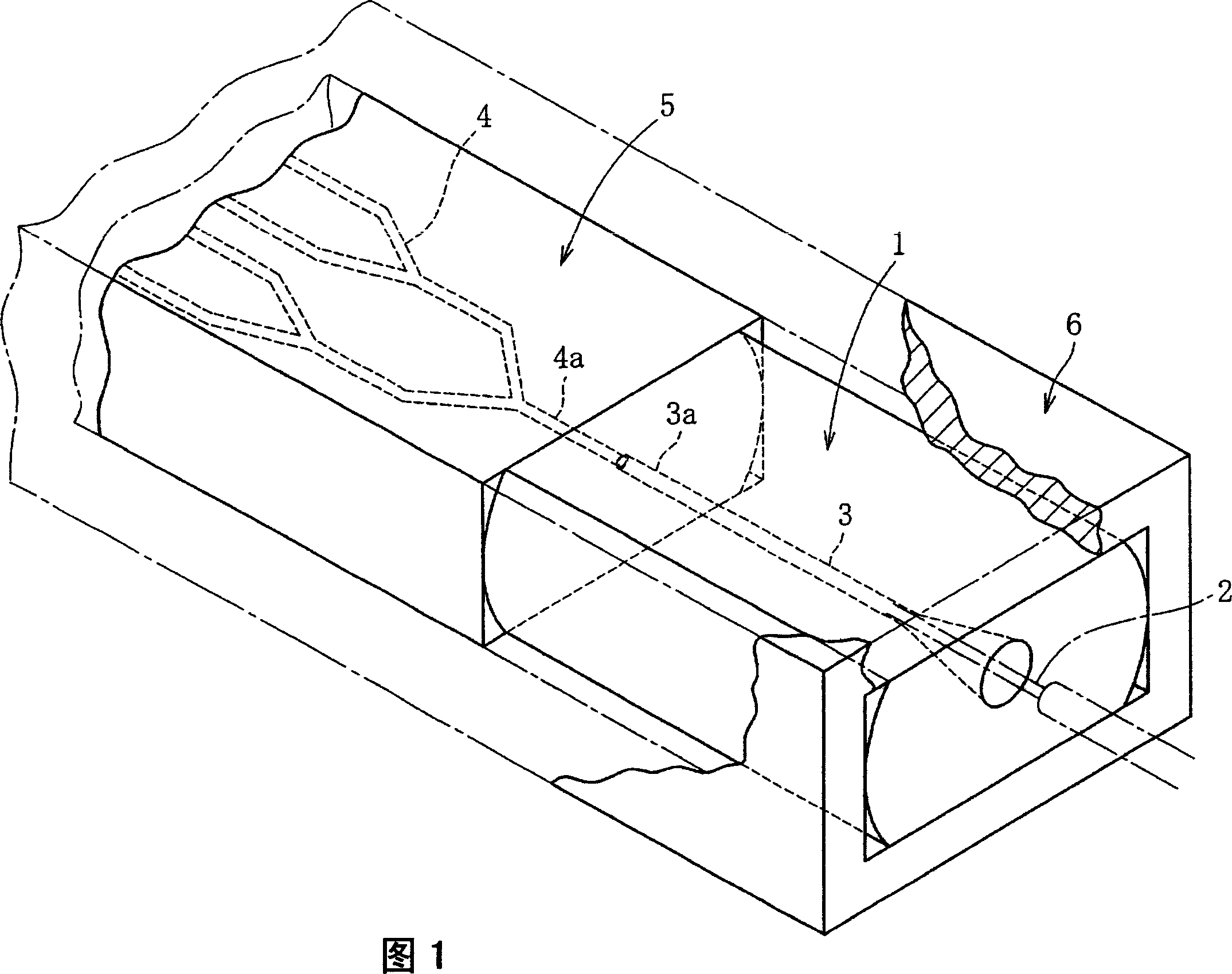
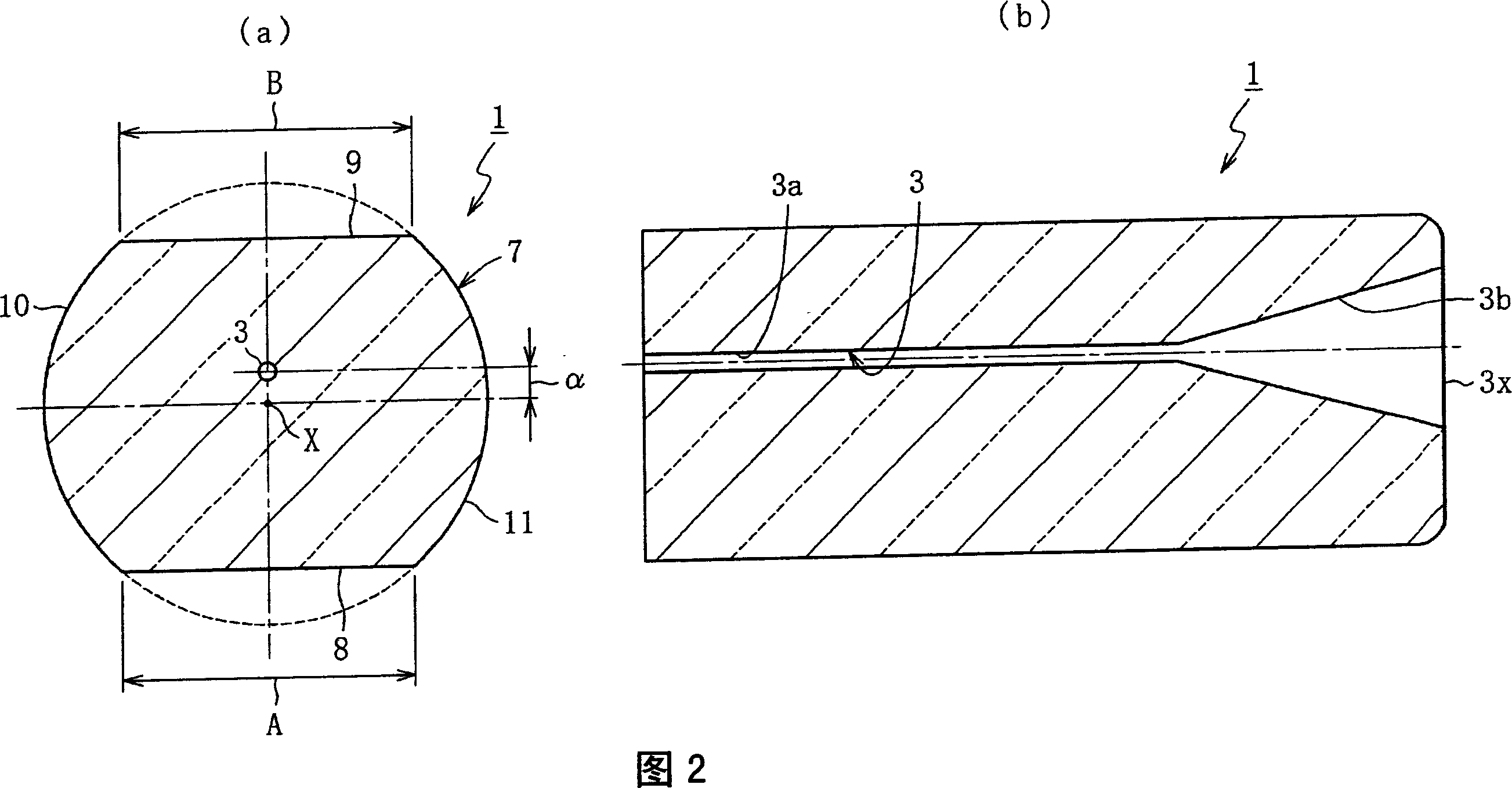
[0046] FIG. 1 illustrates a schematic configuration of a glass capillary for fixing an optical fiber and an optical component connected and fixed thereto according to a first embodiment of the present invention. As shown in the figure, a glass capillary 1 has an insertion hole 3 for inserting and fixing a single-core optical fiber 2, and an optical waveguide element 5 having a core 4 is adhesively fixed in series on one side (tip side) in the optical axis direction thereof. . Then, the adhesively fixed glass capillary 1 and optical waveguide element 5 are housed in a case (holder) 6 and packaged. In this case, the front end 3a of the insertion hole 3 of the glass capillary 1 and the rear end 4a of the core 4 of the optical waveguide element 5 are abutted on the bonding surfaces of both 1 and 5 to be self-aligningly bonded.

[0047] 2( a ) is a longitudinal sectional v...


PUM


Abstract

To provide a capillary for fixing an optical fiber, which can perform alignment work of an optical component such as an optical waveguide element and the capillary with a simple operation, and satisfies the requirement of properly placing the two on the same plane while minimizing the Connect and fix the height difference between the optical part and the capillary when they are placed on the same plane, and encapsulate them with a case without shaking and causing premature deterioration. A fixed glass capillary (1) is connected in series to an optical component (5) having a substantially rectangular cross-section perpendicular to the optical axis (4a), and a fixed optical fiber ( 2) With the insertion hole (3) aligned with the optical axis (4a) of the optical component (5), make the surface side end (9) and the back side end (9) of the outer surface (7) of the glass capillary (1) 8) It is at the same position in the height direction as the outer surface and the inner surface of the optical component (5).

Description

technical field [0001] The present invention relates to a capillary for fixing an optical fiber and a connecting structure for an optical component. Technology on parts. Background technique [0002] As is well known, in the case of aligning and fixing an optical fiber with respect to the optical axis of an optical component such as an optical waveguide element, an optical fiber fixing capillary (hereinafter also simply referred to as a glass capillary) having an insertion hole for inserting and fixing the fiber is used. The glass capillary is fixed in series on the end face of the optical component in a state where the central axis of the insertion hole and the optical axis of the optical component are correctly positioned. In this case, usually, both the optical component and the glass capillary are Set on the same plane of the substrate (or housing or holder). [0003] As a specific example, the following patent document 1 discloses the following case: a glass capillary...

Claims


Application Information

Patent Timeline
Patent Type & Authority Applications(China)
IPC IPC(8): G02B6/36
CPCG02B6/30G02B6/2804G02B6/3801
Inventor 竹内宏和船引伸夫中岛外博
Owner NIPPON ELECTRIC GLASS CO LTD
Learn More