Light source device

A light source device, light source technology, applied in the direction of light source, electric light source, point light source, etc., can solve the problems of size specification limitation and light utilization rate decrease

Inactive Publication Date: 2007-08-15
AU OPTRONICS CORP
View PDF0 Cites 19 Cited by
  • Summary
  • Abstract
  • Description
  • Claims
  • Application Information

AI Technical Summary

Problems solved by technology

This approach is easily limited by size specifications, and may reduce light utilization efficiency

Method used


Image

  • Light source device
  • Light source device
  • Light source device

Examples


Embodiment Construction

[0040] The invention provides a light source device. In a preferred embodiment, the light source device is used for an edge-lit backlight module. The backlight module is usually used as a light source for a liquid crystal display (Liquid Crystal Display).

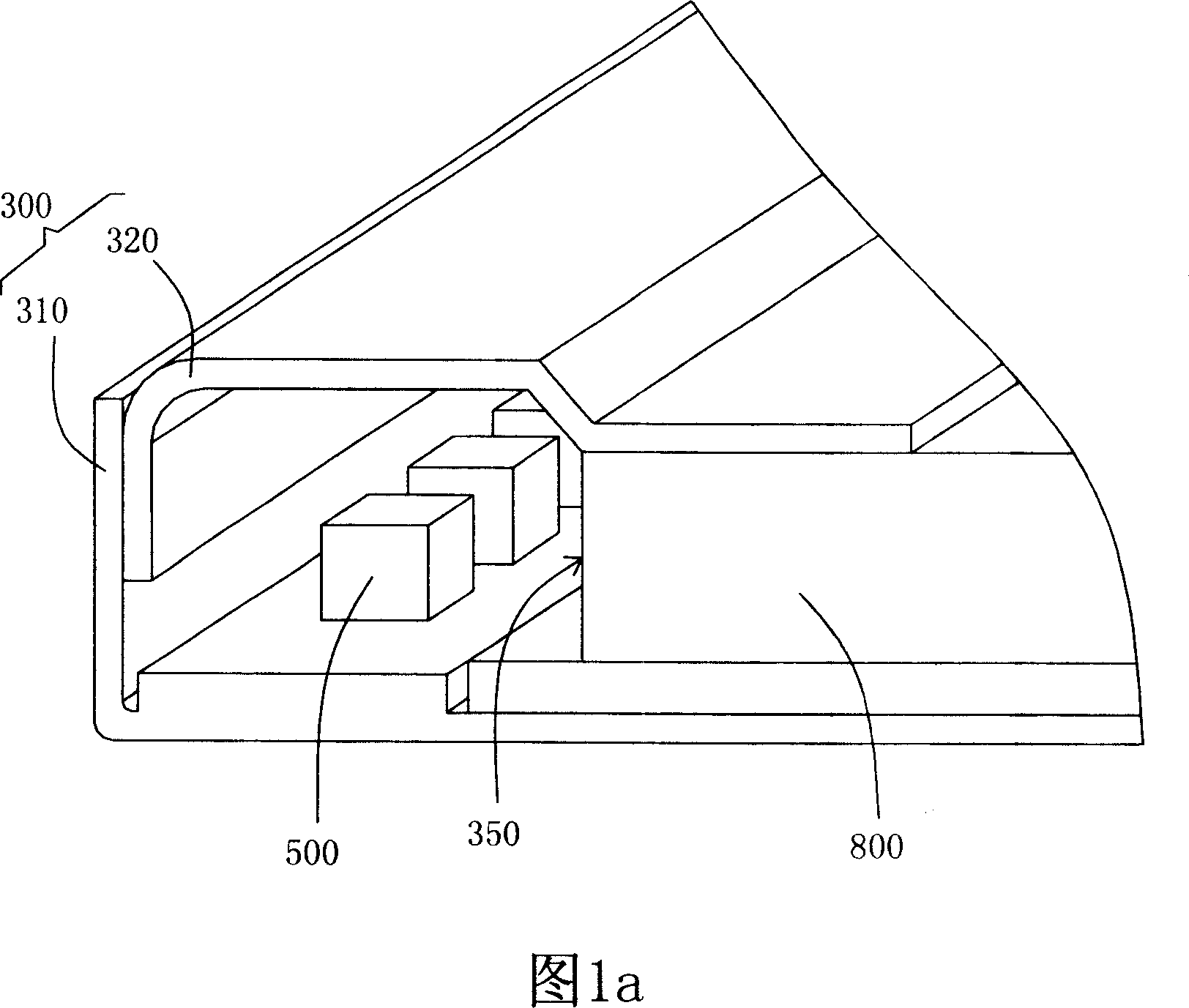
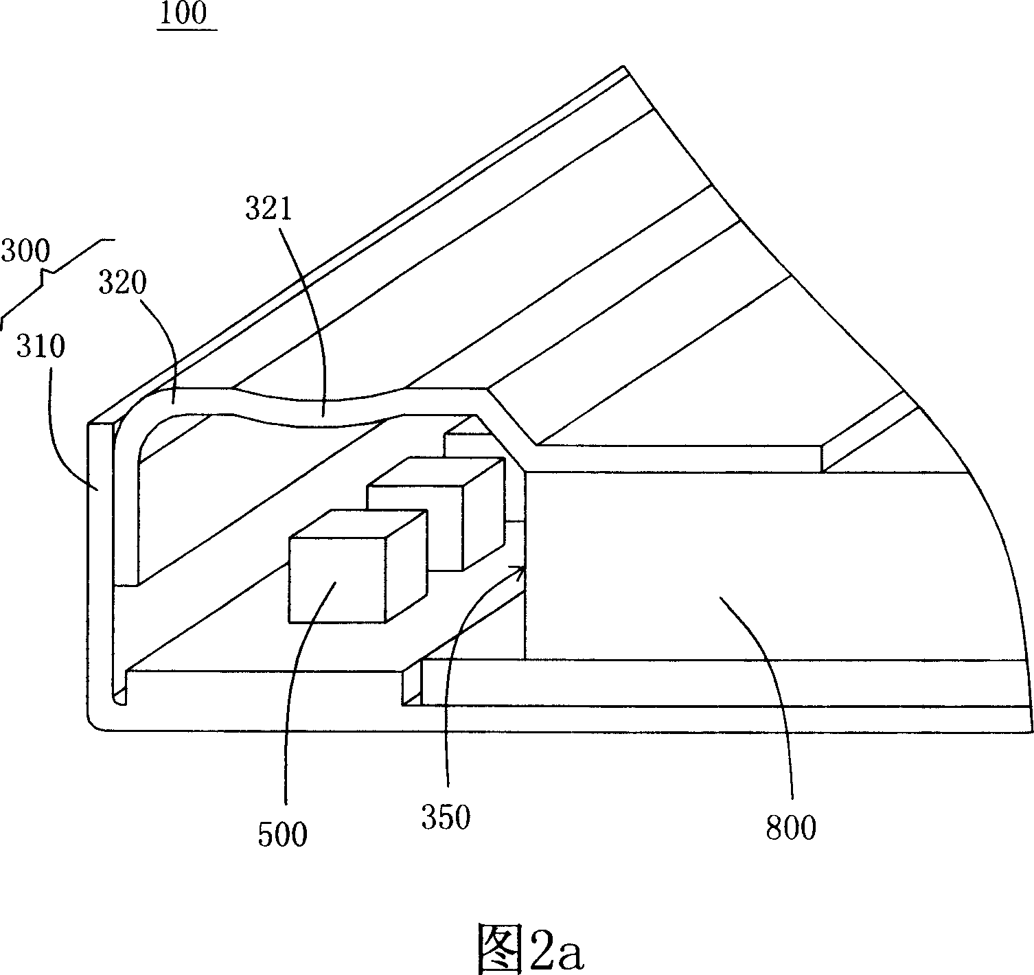
[0041] In the embodiment shown in FIG. 2 a , the light source device 100 of the present invention is preferably disposed on one side of the light guide plate 800 . The light source device 100 includes a mask 300 and a light source 500 . The mask 300 is a semi-closed object disposed along the side of the light source device 100 , including an open end 350 , a first side wall 310 and a second side wall 320 . In a preferred embodiment, the open end 350 is disposed corresponding to the light incident side of the light guide plate 800 . The first sidewall 310 and the second sidewall 320 are located on two opposite sides of the opening end 350 . In the embodiment shown in FIG. 2a, the first side wall 310 refers to the side wa...


PUM

PropertyMeasurementUnit
heightaaaaaaaaaa

Abstract

This light source device for use of one aphototropism module use, wherein, the light source device is set by one side of the light conductive board; the light source device comprises mask film and light source; the mask film has one open end, first side wall and second side wall; the first and second side walls are in relative two sides of open end with reflection part inside; the light source is for light diode inside mask film relative to light reflection part; the mask film comprises light reflection slice down light source; in best example, the first side wall is set relative to open end section with light reflection slice; the light source device also comprises circuit board down light reflection.

Description

technical field [0001] The invention relates to a light source device for a backlight module of a liquid crystal display. Background technique [0002] Liquid Crystal Displays (LCDs) are widely used in various electronic products such as computers, televisions, and mobile phones. A backlight module is one of the important components of a liquid crystal display. The light source device used in the backlight module directly affects the performance and assembly cost of the backlight module. Among them, light emitting diodes (Light Emitting Diodes, LEDs) have become one of the light sources used in liquid crystal displays due to their small size and low energy consumption. In addition, compared with the direct-type backlight module, the edge-type backlight module has attracted attention because it can have a thinner thickness. [0003] A common structure of an edge-lit backlight module includes a light source device, a light guide plate, a reflector plate, and a diaphragm. W...

Claims


Application Information

Patent Timeline
Patent Type & Authority Applications(China)
IPC IPC(8): G02F1/13357F21S2/00F21V19/00F21V7/00F21Y101/02G02F1/1335F21K9/23F21K9/68F21Y115/10
Inventor 杨家骏林玫芬
Owner AU OPTRONICS CORP
Why Eureka
Try Eureka