Molten metal molding machine

A technology of molten metal and forming device, applied in the field of molten metal forming device, can solve the problem that the pressing speed of cylindrical metal material cannot be increased, and achieves the advantages of eliminating the possibility of oxidation of metal material, increasing the pressing speed, and inhibiting oxidation. Effect

A technology of molten metal and forming device, applied in the field of molten metal forming device, can solve the problem that the pressing speed of cylindrical metal material cannot be increased, and achieves the advantages of eliminating the possibility of oxidation of metal material, increasing the pressing speed, and inhibiting oxidation. Effect

CN101020232AInactive Publication Date: 2007-08-22TOYO MACH & METAL CO LTD

Image

  • Molten metal molding machine
  • Molten metal molding machine
  • Molten metal molding machine

Examples


Embodiment Construction

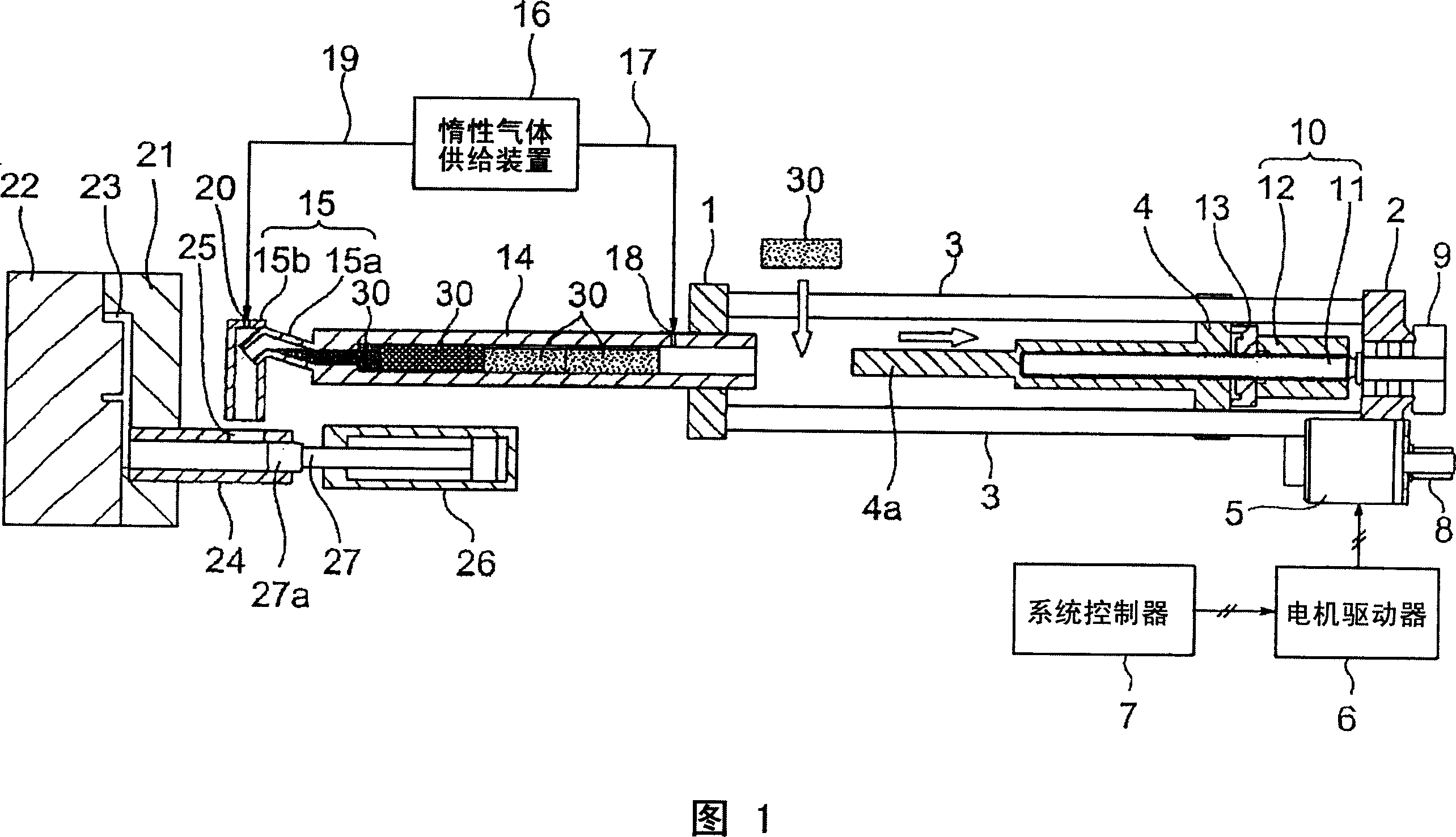
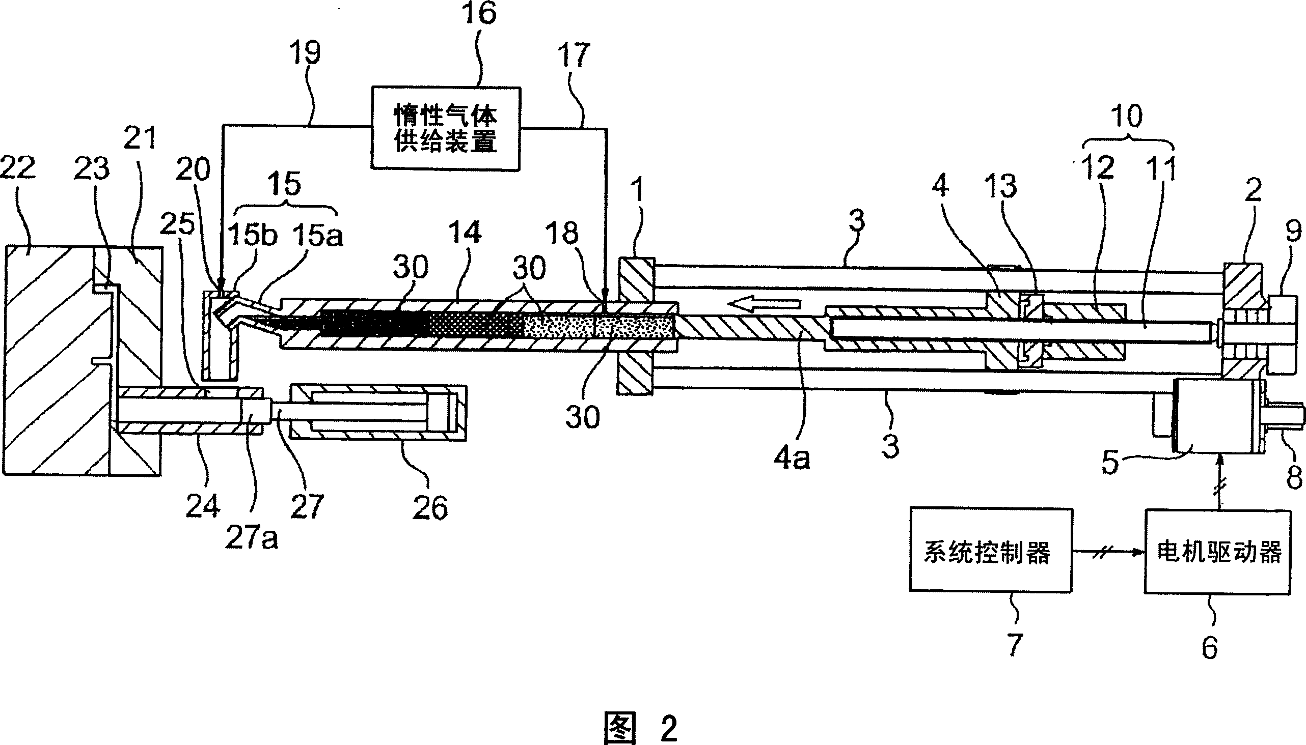
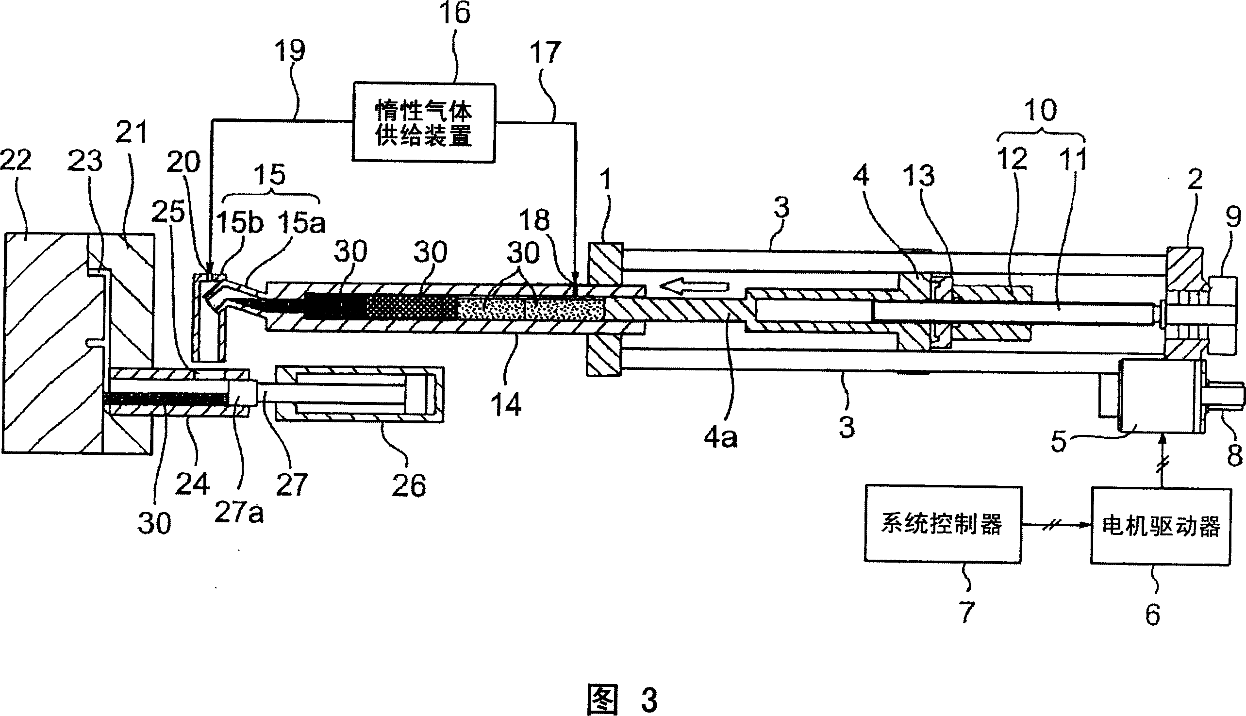
[0033] Embodiments of the present invention will be described below using the drawings. FIGS. 1 to 6 relate to a molten metal forming apparatus according to one embodiment of the present invention (hereinafter referred to as the present embodiment), and FIGS. 1 to 4 are explanatory diagrams schematically showing main parts of the molten metal forming apparatus according to this embodiment.

[0034] In Fig. 1 to Fig. 4, 1 is the first holding plate that can be set forward and backward on the unillustrated guide rail member for the fusion system unit, and 2 is also on the unillustrated guide rail member for the fusion system unit The second holding plate that can be set forward and backward and opposite to the first holding plate, 3 is a plurality of connecting shafts that integrally connect the first holding plate 1 and the second holding plate 2, and 4 is used in the melting system unit not shown The guide rail member is set forwardly and backwardly (or is inserted and guided ...


PUM


Abstract

A molten metal molding machine is provided with a heating cylinder, a linear motion member for successively feeding preheated metal rods into the heating cylinder from its rear end to successively push the metal rods toward a forward end of the heating cylinder, and a heater arranged on the heating cylinder such that the metal rods are gradually molten as they move through the heating cylinder from its rear end toward its forward end. The heating cylinder, the metal rods and a cylindrical forward end portion of the linear motion member are dimensioned such that a predetermined clearance is provided between an inner circumference of the heating cylinder and an outer circumference of each of the metal rods, the cylindrical forward end portion can enter the heating cylinder, and an outer circumference of the cylindrical forward end portion is slidable relative to the inner circumference of the heating cylinder. A preheated new metal rod of a same kind as the metal rods can, therefore, be fully pushed into the heating cylinder irrespective of a fill volume into a mold.

Description

technical field [0001] The present invention relates to a molten metal molding device that injects and fills molten metal (molten metal solution) into a mold cavity, and more particularly relates to a molten metal molding device equipped with a metal melting mechanism that melts metal materials in a heating cylinder. Background technique [0002] As a molten metal molding device that injects and fills molten metal material into the cavity of a mold to obtain a product, there is known a cold chamber die casting machine that is equipped with melting of molten metal materials (such as Al alloys, Mg alloys, etc.) Furnace (crucible), the metal material melted by the melting furnace is measured and pumped up with the amount of each shot as a barrel, and the molten metal (molten metal solution) drawn up is injected into the injection cylinder, and it is passed through the injection push rod The high-speed forward movement injects and fills into the cavity of the mold. In this cold...

Claims


Application Information

Patent Timeline
22 Aug 2007
Publication
CN101020232A
IPC
B22D17/04
CPC
B22D17/30; B22D17/28
Inventors
谷口吉哉