Rotating table

A technology of rotating worktable and worktable, applied in the direction of conveyor control device, conveyor, storage device, etc., can solve the problem of start time delay and so on

Inactive Publication Date: 2007-08-22
ASYST SHINKO INC
View PDF1 Cites 26 Cited by
  • Summary
  • Abstract
  • Description
  • Claims
  • Application Information

AI Technical Summary

Problems solved by technology

[0004] However, in the conventional structure described above, after changing the conveyance direction of the object to be conveyed by changing the rotational posture of the rail member from the carry-in angle to the carry-out angle and carrying it out, when changing the conveyance direction of the next object to be conveyed, It is necessary to perform a recovery operation to return the rotation posture of the guide rail member from the carrying-out angle to the carrying-in angle.
Therefore, this recovery operation becomes a waiting time when changing the direction of the next object to be carried, and as a result, the time to start changing the direction of the object to be carried may be delayed.

Method used


Image

  • Rotating table
  • Rotating table
  • Rotating table

Examples


Embodiment Construction

[0028] Hereinafter, an embodiment of the present invention will be described based on FIGS. 1 to 12.

[0029] (Overview of the transportation system)

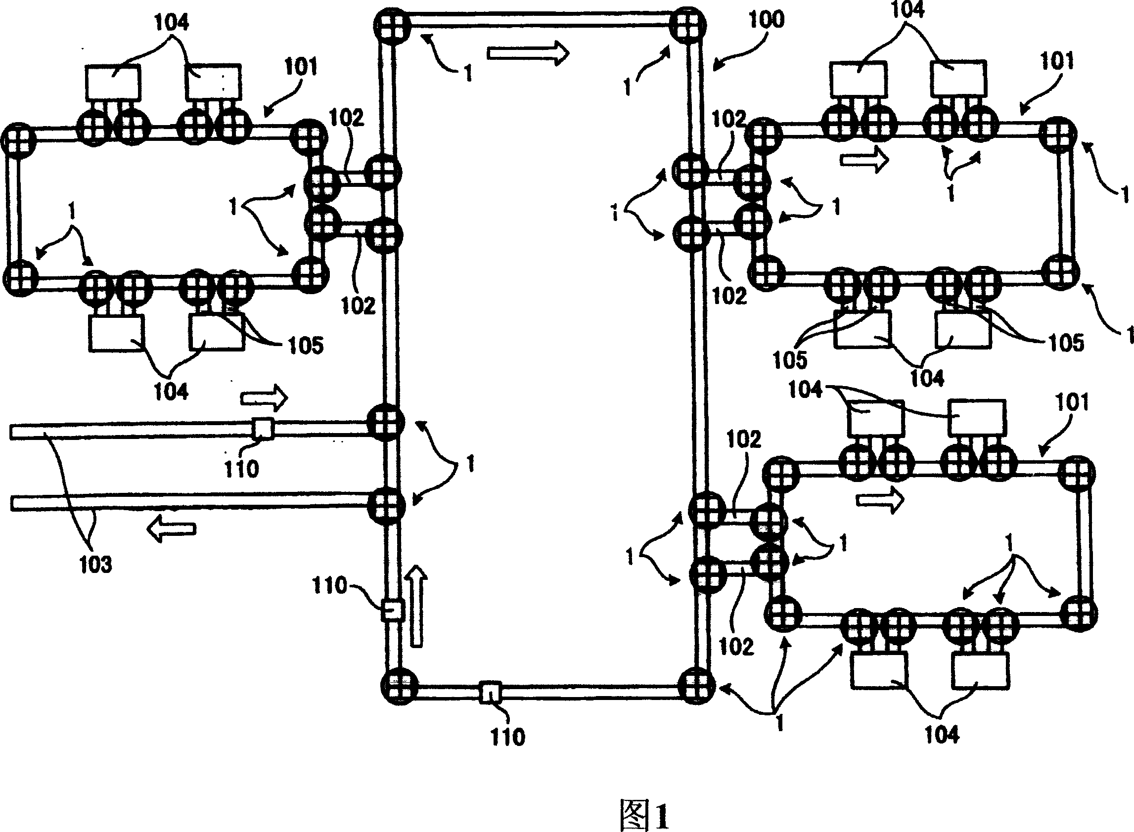
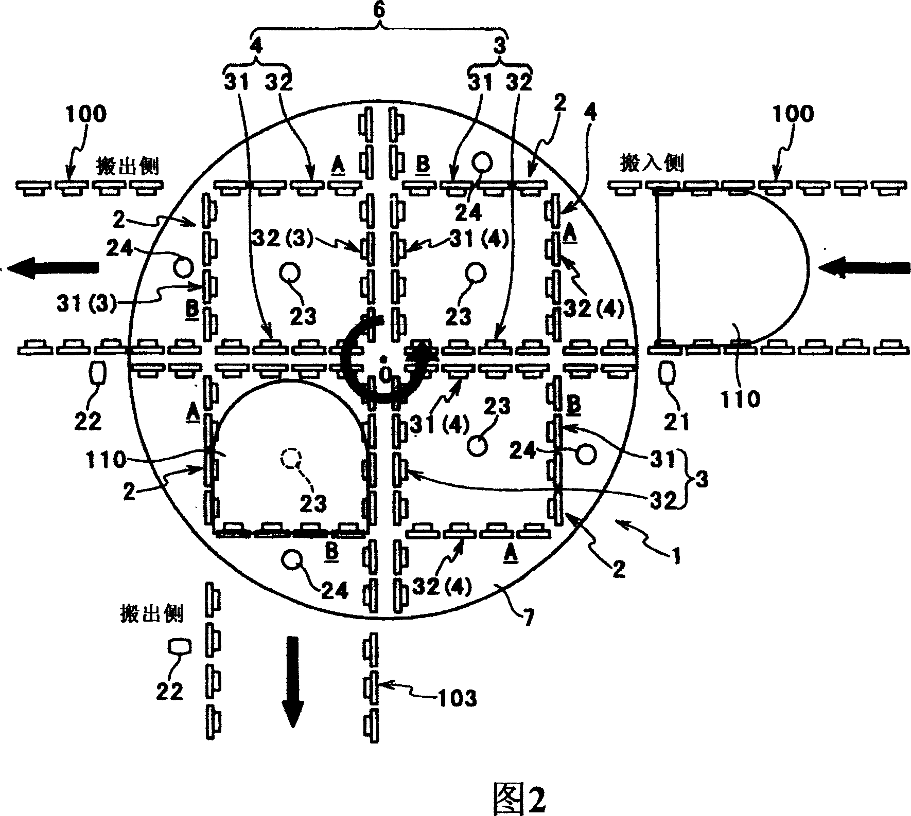
[0030] The rotary table according to this embodiment can change the conveying direction of the carriage 110 (object to be conveyed) conveyed on the conveying rail, and is installed in the conveying system shown in FIG. 1, for example. The conveying system includes: an inter-process roller conveyor track 100 arranged in a predetermined area to communicate between processes, an in-process roller conveyor track 101 arranged around the inter-process roller conveyor track 100, and a connection The other process shown in the figure (including the roller conveyor track 100 between the processes) and the roller conveyor track 103 communicate with the roller conveyor track 100 between the processes.

[0031] The roller conveyor track 101 and the inter-process roller conveyor track 100 in the above-mentioned process communicate with each oth...


PUM


Abstract

The invention provides a revolving table, which can start to change the direction of the movement of a conveyed object in a very short time. The revolving table is provided with inlet side ends (A) and outlet side end (B) respectively communicating with the inlet side and the outlet side of a conveying track; a first track (3) and a second track (4) used for conveying the conveyed object from the inlet side ends (A) to the outlet side ends (B); a worktable component (7) for arranging the first track (3) and the second track (4); a worktable rotation mechanism (8) used for rotating the worktable component (7) and stopping the worktable component at any angle of rotation; a worktable rotation control mechanism used for controlling the rotation of the conveyed object on the first track (3) and the second track (4) in the conveying direction. The first track (3) and the second track (4) are arranged on the worktable component (7) in the following way: when the conveying direction is set, either the inlet side end (A) of the first track (3) or the inlet side end (A) of the second track communicates with the inlet side of the conveying track.

Description

Technical field [0001] The invention relates to a rotating workbench for changing the conveying direction of a conveyed object. Background technique [0002] Conventionally, as such a device, there is, for example, a device described in Patent Document 1. Specifically, the guide rail member is rotatably installed on the direction changer for changing the direction of the loading rail, and when it is in the rotating posture of the loading angle, one end of the rail member is aligned with the loading rail on the loading side, and when the loading is performed In the angular rotation posture, the other end of the rail member is aligned with the carry-in rail on the carry-out side. Therefore, in the conventional rotary table, by changing the rotation posture of the rail member to the carry-in angle and the carry-out angle, the object can be transported while maintaining a certain posture with respect to the carry-in rail. [0003] Patent Document 1: Special Form 2003-506289 Bulletin ...

Claims


Application Information

Patent Timeline
Patent Type & Authority Applications(China)
IPC IPC(8): B65G47/52B65G47/54B65G47/68B65G37/00B65G47/24B65G43/00H01L21/677
CPCB65G2201/0297B65G47/80B65G43/08B65G47/54B65G43/00B65G1/00
Inventor 久德千三椿达雄村田正直
Owner ASYST SHINKO INC
Why Eureka
Try Eureka