Drag for service elevator

An elevator traction machine and traction machine technology, applied in the field of elevator traction machines, can solve the problems of reduced traction machine efficiency, poor coaxial precision, center offset, etc., to improve braking stability and efficacy, and use Long life, correct positioning effect

Inactive Publication Date: 2007-08-22
CHANGSHU CANON ELEVATOR ACCESSORIES
View PDF0 Cites 5 Cited by
  • Summary
  • Abstract
  • Description
  • Claims
  • Application Information

AI Technical Summary

Problems solved by technology

The above-mentioned motor 6 is installed horizontally, that is, the motor 6 is placed horizontally on the traction machine frame 61, and the motor frame 63 is used to adjust the installation height of the motor 6. However, it is found during actual use that this installation method It is difficult to ensure that the output shaft of the motor 6 and the worm shaft of the reducer 4 are on the same axis for the horizontal assembly of the traction machine of the small sundry elevator, that is, there is an error in the coaxial precision between the two. Too large will cause the whole machine to vibrate during the working process and will be accompanied by noise, which will affect the product quality of the traction machine. Moreover, it will also make the position of the brake and the brake disc uncertain, and the brake contact surface will change. The braking gap of the brake is asymmetrical to the left and right, and the center shifts to affect the braking effect of the traction machine; in addition, due to poor coaxial precision, the efficiency of the traction machine will also be reduced

Method used


Image

  • Drag for service elevator
  • Drag for service elevator

Examples


Embodiment Construction

[0018] Through the applicant's detailed description of the embodiments below, it will be more helpful to understand the essence of the present invention, and the advantages and positive effects of the present invention will be clearer, but the embodiments should not constitute any limitation to the solution of the present invention.

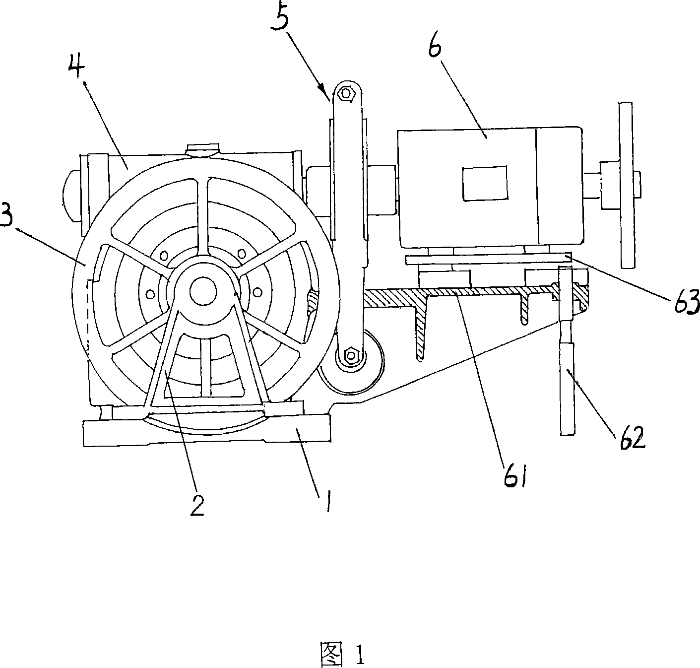
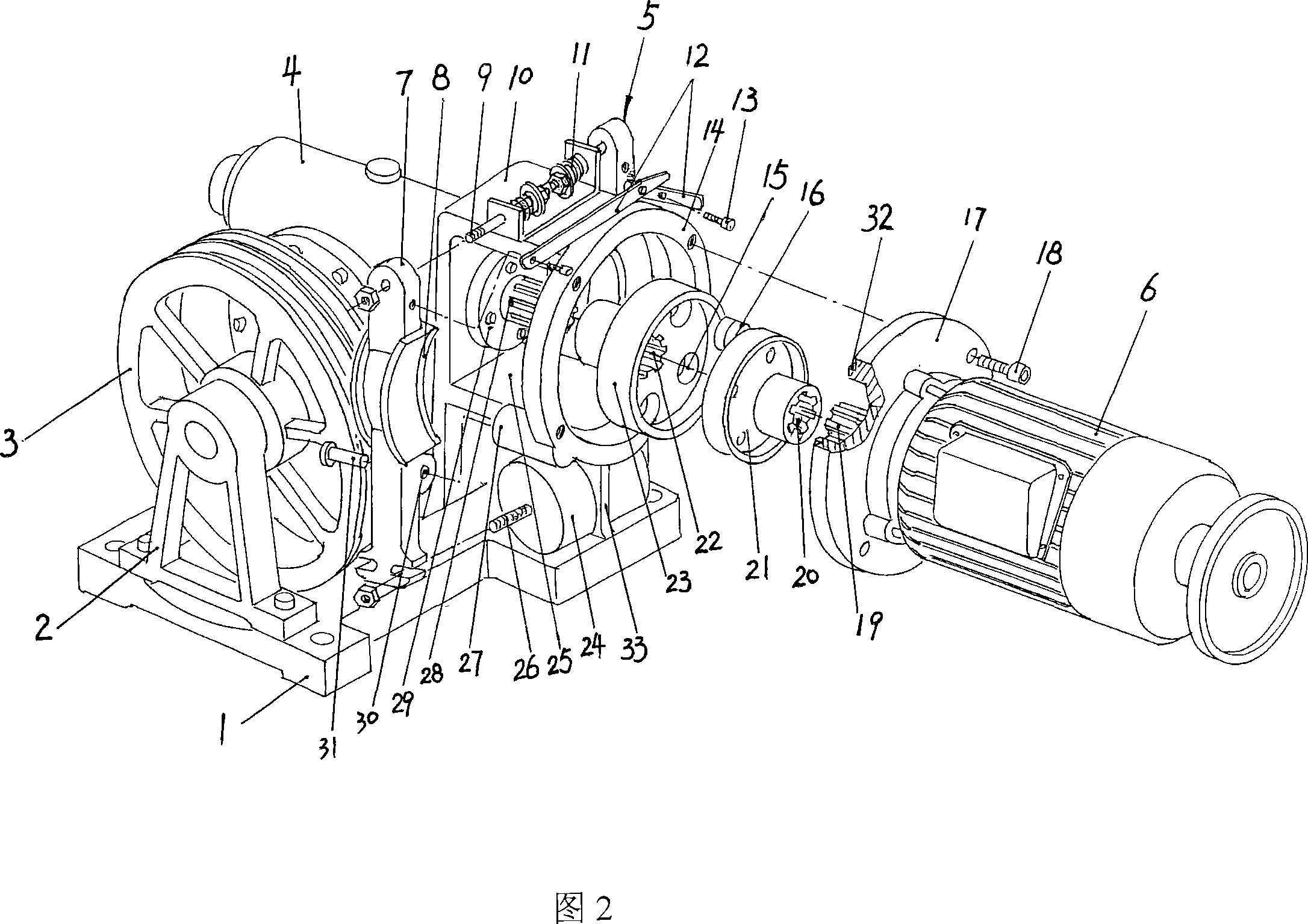
[0019] Please refer to Fig. 2, the motor 6 of the present invention is provided with a motor flange seat 17 at the end near one end of the output shaft 19, the cross-sectional shape of the motor flange seat 17 is disc-shaped, and the output shaft 19 is located At the center of the motor flange seat 17, and at the edge of the vertical disc-shaped motor flange seat 17, it is narrowed to form a tooth mouth for tight fitting with the inner ring of the motor flange seat ring 14 for positioning 32. The reducer 4 of the present invention is integrally formed with a traction machine race frame 10 on the box near the worm shaft 28, and a brake disc chambe...


PUM


Abstract

The present invention is one kind of drag for small service elevator, and belongs to the field of elevator driver. The drag for small service elevator includes motor, shaft coupling, speed reducer, brake disc, dragging wheel, jig, pedestal and brake, and features the output shaft of motor with flange, the drag seat of the speed reducer, and the flange seat for the motor to be fixed on through the flange seat. The drag for small service elevator of the present invention has the advantages of simple installation, correct location, high coaxiality between the output shaft of the motor and the worm shaft of the speed reducer, high braking stability and effect, etc.

Description

technical field [0001] The invention discloses an elevator traction machine, in particular a small debris elevator traction machine which is specially used for transporting sundries and whose load capacity does not exceed 350Kg, and belongs to the technical field of lifting facilities. Background technique [0002] In the prior art, the traction machines for small sundry elevators with a loading capacity of no more than 350Kg, such as the well-known F100K and F120K series in the industry, have a structure as shown in Fig. The shaft joint is connected with the motor 6 to drive the reducer 4, the traction sheave 3 connected with the reducer 4, the hanging foot 2 pivoted on the shaft end of the power output shaft of the reducer 4 to support the traction sheave 3, The base 1 extending from the bottom of the reduction box of the reducer 4 and the brake 5 used to brake the rotation of the traction wheel 3, wherein the motor 6 is installed on the traction machine frame 61 through t...

Claims


Application Information

Patent Timeline
Patent Type & Authority Applications(China)
IPC IPC(8): B66B11/04
Inventor 陈惠良
Owner CHANGSHU CANON ELEVATOR ACCESSORIES
Why Eureka
Try Eureka