Power device for air jet loom

A power unit, air-jet loom technology, applied in looms, textiles, textiles and papermaking, etc., can solve the problems of poor braking stability, low transmission efficiency, etc., achieve convenient adjustment and maintenance, improve transmission efficiency, and simplify the structure. Effect

Inactive Publication Date: 2014-08-06
HANGZHOU CHUANGXING WEAVING EQUIP TECH
View PDF7 Cites 6 Cited by
  • Summary
  • Abstract
  • Description
  • Claims
  • Application Information

AI Technical Summary

Problems solved by technology

[0004] It is these reasons that lead to the problems of low transmission efficiency and poor braking stability in the existing air-jet looms

Method used


Image

  • Power device for air jet loom

Examples


Embodiment Construction

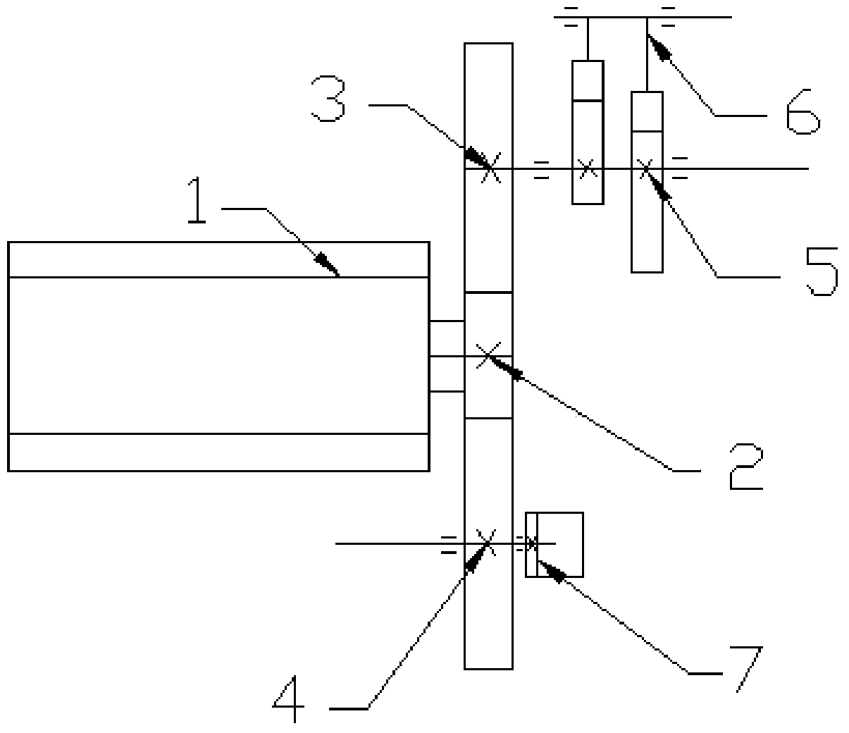
[0012] Such as figure 1 As shown, a power device of an air-jet loom includes a servo motor 1, and a main drive gear 2 is installed on the output shaft of the servo motor 1, and the main drive gear 2 is simultaneously connected with the beating-up transmission gear 3 and the opening transmission. Gear 4 meshes and drives, and the main drive gear, the beating-up drive gear and the open drive gear are all spur gears. Described opening transmission gear 4 is installed on the opening transmission gear shaft, and power-off brake 7 is installed on the described opening transmission gear shaft, and described beating-up transmission gear 3 is installed on the transmission shaft, and beating is also installed on the transmission shaft. Weft conjugate cam 5, the servo motor 1 drives the beating transmission gear 3 and the shedding transmission gear 4 to rotate through the main drive gear 2 simultaneously, the shedding transmission gear 4 drives the shedding mechanism to move to realize t...


PUM


Abstract

The invention discloses a power device for an air jet loom. The power device for the air jet loom comprises a servo motor, wherein a primary driving gear is arranged on the output shaft of the servo motor and is in mesh transmission with a beating-up transmission gear and an open transmission gear simultaneously, the open transmission gear is arranged on an open transmission gear shaft, a power-off brake is arranged on the open transmission gear shaft, the beating-up transmission gear is arranged on a transmission shaft, and a beating-up conjugate cam is arranged on the transmission shaft. By means of the gear transmission structure formed by the primary driving gear, the beating-up transmission gear and the open transmission gear, transmission efficiency is increased, the structure is simplified, and regulation and maintenance are convenient.

Description

technical field [0001] The present invention relates to a power unit for an air-jet loom. Background technique [0002] In the prior art, the power source of the power device providing power for the air-jet loom is a three-phase asynchronous motor. In this power device, the three-phase asynchronous motor transmits the power to the driving shaft of the loom through the first-stage transmission belt. Since the power is transmitted through the transmission belt, the tension of the transmission belt is not enough to transmit power normally and effectively when the transmission belt is loose, which causes the loom to start. There is a sliding phenomenon in the process, which obviously increases the power transmission loss. [0003] In addition, an electromagnetic braking mechanism is provided on the main shaft of the loom for braking the loom. Therefore, the transmission mechanism and system control of the power unit adopt electromagnetic clutch structure. This makes the struc...

Claims


Application Information

Patent Timeline
IPC IPC(8): D03D47/30D03D51/00
Inventor 梁景波杨延增国保才
Owner HANGZHOU CHUANGXING WEAVING EQUIP TECH
Why Eureka
Try Eureka