Method for measuring pilot frequency in wideband radio system

A pilot frequency measurement, broadband wireless technology, applied in the transmission system, communication between multiple stations, transmission monitoring and other directions, can solve the problem of terminal computing overload and other problems, reduce equipment power consumption, reduce complexity, computing The effect of load reduction

Active Publication Date: 2011-07-20
SHANGHAI ULTIMATE POWER COMM TECH
View PDF3 Cites 0 Cited by
  • Summary
  • Abstract
  • Description
  • Claims
  • Application Information

AI Technical Summary

Problems solved by technology

[0004] Aiming at the problem in the prior art that the calculation load of the terminal is too heavy due to the need to measure each pilot signal when performing pilot frequency measurement of a broadband wireless system, the present invention proposes a method that can reduce the burden on the terminal and is applied in the broadband wireless system. Pilot measurement method for calculating load

Method used


Image

  • Method for measuring pilot frequency in wideband radio system
  • Method for measuring pilot frequency in wideband radio system
  • Method for measuring pilot frequency in wideband radio system

Examples


Embodiment Construction

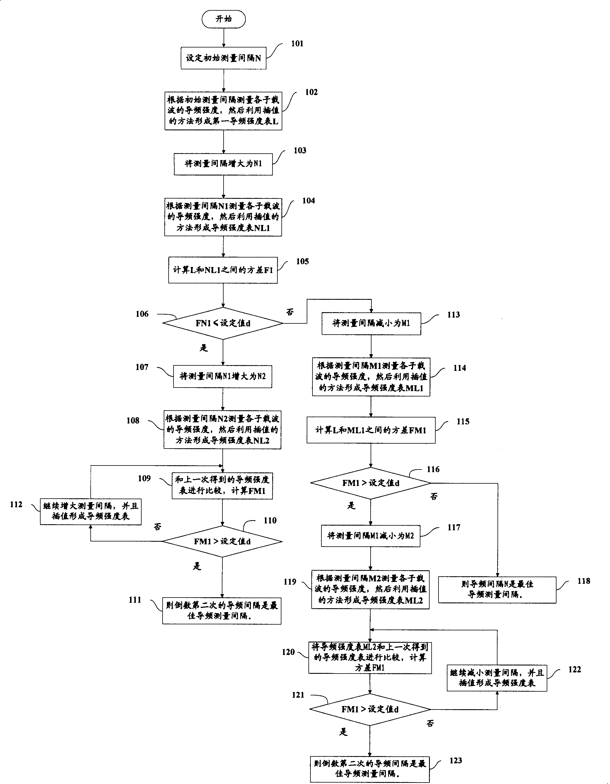
[0040] In the present invention, it is considered that the variation of different pilot symbol strengths in a frequency band of a certain bandwidth is continuous with the variation of the frequency, thus, it is possible to select a certain interval for measurement, and then adopt a certain interpolation method to obtain the intensity of the entire frequency band Pilot strength or other information.

[0041] figure 1 is a flow chart of the pilot frequency measurement method according to the first embodiment of the present invention. In the case of performing pilot measurement according to the scheduling requirements or handover requirements of the system, first, in step 101, the broadband mobile communication system sets an initial measurement interval. For example, if the initial interval is set to 60 kHz, if the center frequency interval between two adjacent subcarriers is 15 kHz, then the initial interval is equivalent to measuring the pilot signal every 4 subcarriers.

...


PUM


Abstract

A method for measuring pilot frequency in wideband radio system includes measuring pilot frequency intensity of each sub-carrier wave, using interpolation means to obtain pilot frequency intensity data of full band and writing data in the first pilot frequency intensity table, changing measurement interval to obtain new pilot frequency intensity and new pilot frequency intensity data, writing newdata in the second pilot frequency intensity table, comparing two said tables and writing data in the second table onto the first one to decrease said interval if difference of two said tables is greater than a set value or otherwise writing data in the second table onto the first one to increase said interval.

Description

technical field [0001] The invention relates to a method for measuring a pilot signal, in particular to a method for measuring a pilot in a broadband wireless system. Background technique [0002] The pilot signal is an unmodulated, direct-sequence spread-spectrum signal continuously transmitted by each base station, and it is mainly used to synchronize all terminals working in the coverage area of ​​the base station. In the 3G system, there is only one pilot signal, and terminal measurement only needs to test one pilot signal to obtain relevant information of the entire cell. However, in the evolved 3G system, due to the adoption of wider bandwidths, such as 5MHz, 10MHz, 20MHz and other bandwidth settings, the results measured by the terminal on a certain subcarrier cannot represent the characteristic parameters of the entire frequency band (such as the path of the entire frequency band loss, transmit power, etc.). Therefore, in the latest evolved system, it is necessary ...

Claims


Application Information

Patent Timeline
Patent Type & Authority Patents(China)
IPC IPC(8): H04B7/26H04B17/00
Inventor 王文清谢永斌胡海静张大钧
Owner SHANGHAI ULTIMATE POWER COMM TECH
Why Eureka
Try Eureka