Yarn braking body

A braking body and yarn technology, applied in thin material processing, textiles, papermaking, knitting, etc., can solve the problem of time-consuming replacement of the holding structure, and achieve the effect of easy replacement and reasonable cost

Inactive Publication Date: 2007-08-22
IRO AB
View PDF0 Cites 2 Cited by
  • Summary
  • Abstract
  • Description
  • Claims
  • Application Information

AI Technical Summary

Problems solved by technology

Due to the replacement of the above-mentioned holding structure is time-consuming

Method used


Image

  • Yarn braking body

Examples


Embodiment Construction

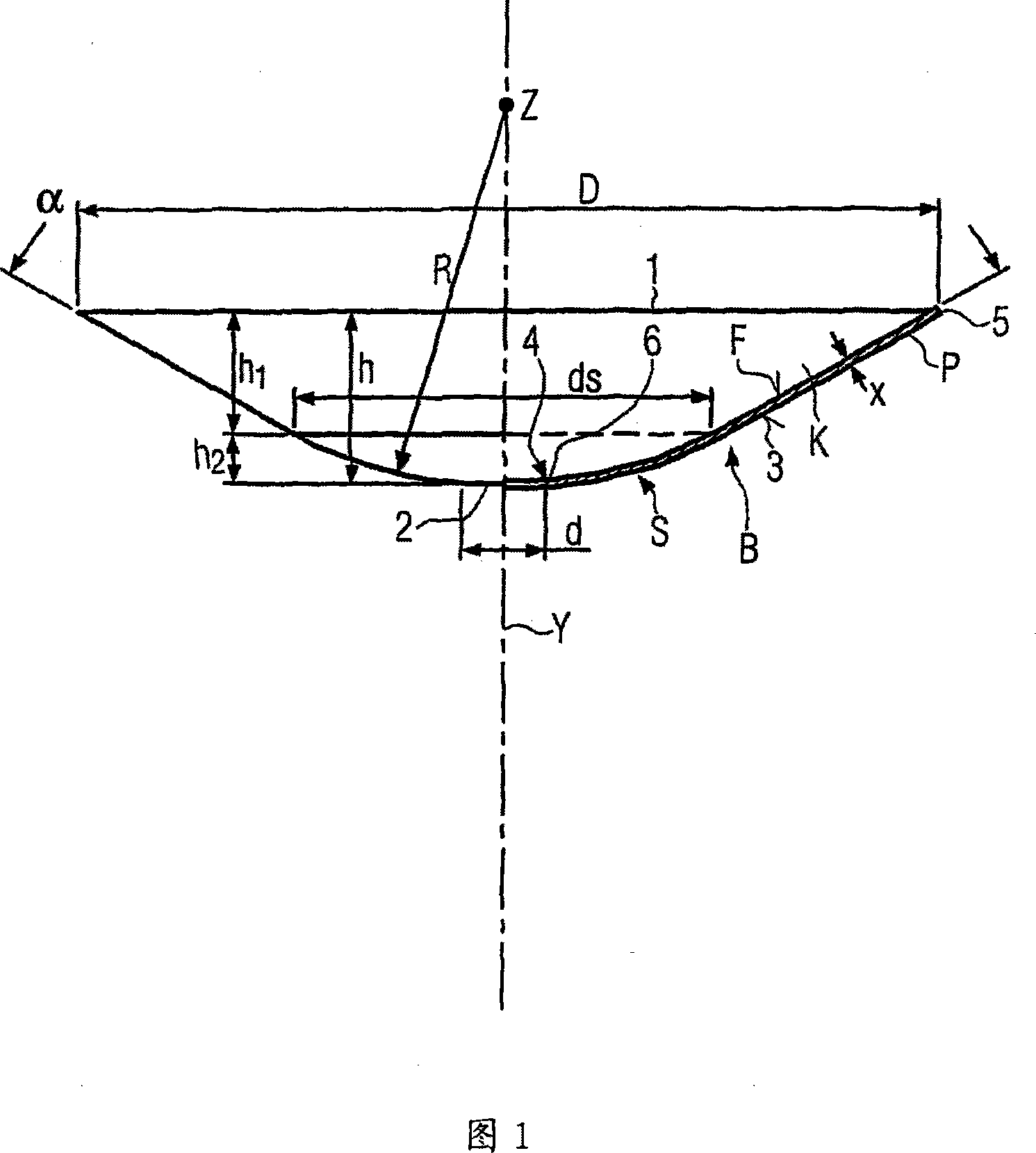
[0019] Conveniently, Fig. 1 provides a yarn braking body B of a knitting yarn feeding device (not shown) which cooperates with a circular extraction edge of a drum-shaped yarn storage body of the knitting yarn feeding device so that when the The yarn is driven or loaded with a small braking force when the yarn is extracted inwardly by the extraction edge and simultaneously rotates like the hands of a clock. Thus, the yarn braking body is arranged coaxially with the storage body from the front side opposite the extraction side and remains suspended so that it is centered on the extraction side but still remains capable of a certain movement. The yarn braking body B is a piece of plastic material, for example made of a thermoplastic P like polyester, PET or PVC. For example, the yarn braking body B is produced by vacuum setting on a forming die, sometimes even by thermal vacuum setting.

[0020] The yarn braking body B consists of a right frustoconical shell K and a spherical s...


PUM


Abstract

A yarn braking body B is a flexible frustocone coat K made from plastic material P and has a circumferentially continuous braking surface F which is defined by a part of the inner surface of the frustocone coat. The yarn braking body B has a circumferentially continuous support part S at the small diameter end 2. The support part S is spherical and one piece with the frustocone coat K and is made from the plastic material of the yarn braking body B such that the centre Z of the sphere lies in the axis Y of the frustocone coat K which axis Y is prolonged beyond the large diameter end 1.

Description

technical field [0001] The invention relates to a yarn braking body according to the preamble of claim 1 . Background technique [0002] In practically known knitting yarn feeding devices there is a yarn braking body which is a standard frustoconical shell made of smooth vacuum-set plastic material. The support is a support ring which snaps securely over the small diameter end of the frusto-conical shell and is mounted as a separate part, the support including anchor holes for hooking tension springs extending radially outward from the support And the brake body is held in a coaxial running position in contact with the circular withdrawal rim of the yarn storage body of the knitting yarn feeding device. Such holding structures with tension springs are complex in construction. Manufacturing and assembling such a support on the yarn braking body requires several work steps. The knitting yarn is unwound from the storage body through the extraction edge and along the yarn arr...

Claims


Application Information

Patent Timeline
Patent Type & Authority Applications(China)
IPC IPC(8): B65H51/22D04B15/44
CPCD04B15/44D03D47/366D04B15/484
Inventor 库尔特·阿尔内·贡纳尔·雅各布松
Owner IRO AB
Why Eureka
Try Eureka