Measuring strip and system for determining the motion of a moving object

A technology of moving objects and signal strips, applied in the field of systems with such signal strips, can solve the problem that the position determination is only based on the magnetic principle, etc., and achieve the effect of improving functional safety.

Inactive Publication Date: 2007-08-22
THYSSENKRUPP ELEVATOR AG (DE)
View PDF4 Cites 11 Cited by
  • Summary
  • Abstract
  • Description
  • Claims
  • Application Information

AI Technical Summary

Problems solved by technology

The disadvantage of this device is therefore that the determination of the position of the me

Method used


Image

  • Measuring strip and system for determining the motion of a moving object
  • Measuring strip and system for determining the motion of a moving object
  • Measuring strip and system for determining the motion of a moving object

Examples


Embodiment Construction

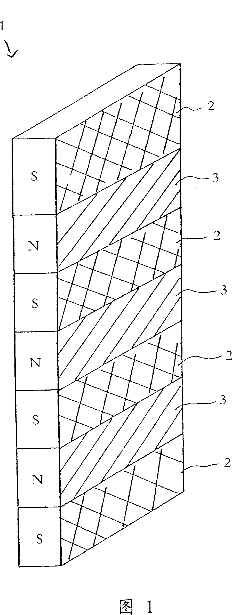
[0051] FIG. 1 shows a signal strip 1 according to the invention in a partial perspective view. The signal strip 1 has a longitudinal extension along which the individual signal segments 2 , 3 are arranged. Alternating signal segments 2, 3 respectively comprise three different pieces of information which are respectively based on the physical properties of the signal strip, namely optical properties, magnetic properties, and properties concerning the reflection of electromagnetic waves. In particular, the signal segments are designed in such a way that information on the basis of the same property differs from one another in alternating signal segments, as explained below.

[0052] In the exemplary embodiment shown in FIG. 1 , all respectively every second following signal segment 2 are designed with magnetic south polarization, identified by the letter "S". Furthermore, the signal section 2 is covered by a copper layer, as indicated by cross-hatching. Thanks to these copper ...


PUM


Abstract

The elongated signal strip (1) has signal sections (2,3) along its longitudinal extent which contain at least two different informations, dependent upon an optical property, a magnetic property or a property relating to a reflection of electro-magnetic waves of the signal section, determinable by at least one sensor device (7,8,9). Information dependent upon the same property are different from one another in alternating signal sections. The signal strip is introduced in a system for determining a movement condition, particularly of a lift cage (6).

Description

technical field [0001] The present invention relates to an elongated signal strip with a plurality of signal segments along its longitudinal length and to a system with such a signal strip for determining the state of motion of a moving object. Background technique [0002] In the case of multiple moving objects, e.g. within the scope of automation technology or conveyor technology, or in the form of elevators, the determination and control of the speed of the moving objects is decisive in order to ensure efficient work processes and the safety of personnel meaning. [0003] Mechanical safety systems have been tested for decades in the case of moving objects in the form of elevator cars of elevators, where, in addition to conventional traction cables, another cable is fixed to the part running together (e.g. the car), the part Deflected by one or more guide rollers. [0004] Such a safety system is described, for example, in DE 299 12 544 U1 in the form of a centrifugal fo...

Claims


Application Information

Patent Timeline
IPC IPC(8): B66B1/34G01B7/02
CPCG01D3/08B66B1/3492G01D5/2451
Inventor 弗兰克·达德沃尔夫冈·迈斯纳格哈德·苏姆
Owner THYSSENKRUPP ELEVATOR AG (DE)
Why Eureka
Try Eureka