X-ray fluroscopic device

An X-ray and optical image technology, applied in the field of industrial X-ray fluoroscopy devices, can solve problems such as reducing work efficiency

Inactive Publication Date: 2007-08-22
SHIMADZU SEISAKUSHO CO LTD
View PDF1 Cites 3 Cited by
  • Summary
  • Abstract
  • Description
  • Claims
  • Application Information

AI Technical Summary

Problems solved by technology

This operation reduces work efficiency

Method used


Image

  • X-ray fluroscopic device
  • X-ray fluroscopic device
  • X-ray fluroscopic device

Examples


Embodiment Construction

[0031] Specific embodiments of the present invention are described by the following figures.

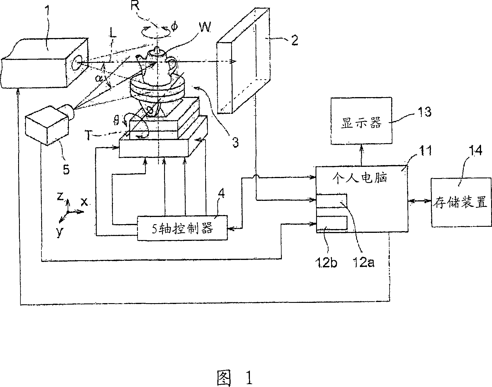
[0032] FIG. 1 shows a block diagram of an embodiment of the present invention, that is, a view showing a combination of a schematic diagram showing a mechanical configuration and a block diagram of a system configuration.

[0033] The X-ray detector 2 is arranged horizontally opposite to the X-ray source 1 , and a sample stage 3 for placing a see-through object W is inserted between them. The sample stage 3 includes a moving device, which can move from the X-ray optical axis direction of the X-ray source 1 (in the X-axis direction), on the Y-axis direction perpendicular to the X-axis direction on the horizontal plane, and in the vertical direction. Move in the direction of the Z axis. Further, the sample stage also includes a rotating device that rotates (Φ) around a rotating central axis R parallel to the Z axis, and also includes a tilting device that tilts (θ) around a tilting ce...


PUM


Abstract

A fluoroscope capable of recognizing the examining direction or position of a fluoroscopic object intuitively and easily at all times without requiring a work for confirming the examining position or direction by reducing the fluoroscopic magnification. An optical camera (5) for photographing a fluoroscopic object W on a sample stage (3) is provided, the fluoroscopic object W is photographed by the optical camera (5) in a plurality of postures by driving the sample stage (3) prior to fluoroscopic work and the optical images are stored in a storage device (14). During fluoroscopic operation, an optical image O closest to the image of the fluoroscopic object W viewed from the examining direction at the current moment in time is selected from among the optical images stored in the storage device (14) and displayed on a display (13) so that the examining direction can be recognized intuitively. The examining direction can also be recognized intuitively when a marker M indicative of the position of the optical axis L of X-rays is displayed superimposingly in addition to the optical image O.

Description

technical field [0001] The present application relates to an industrial X-ray fluoroscopy device, and more particularly, relates to an X-ray fluoroscopy device suitable for non-destructively observing internal damage of objects such as aluminum castings and the like. Background technique [0002] The X-ray fluoroscopy device that fixes the sample stage of the object to be inspected (see-through object) is inserted between the X-ray source and the X-ray detector and moves and rotates is a device known so far for non-destructive detection of internal damage such as aluminum castings (such as See Patent Document 1). [0003] In this type of device, since the position and attitude of the fluoroscopic object depend on the position and rotation angle of the sample stage, the operator usually observes the X-ray fluoroscopic image through the window on the cover of the device or checks the Seeing through the position and attitude of the object and simultaneously operating the drive...

Claims


Application Information

Patent Timeline
Patent Type & Authority Applications(China)
IPC IPC(8): G01N23/04
CPCG01N23/223G01N2223/076
Inventor 龟川正之国嘉夫
Owner SHIMADZU SEISAKUSHO CO LTD
Why Eureka
Try Eureka