

Liquid distributor and liquid collector for chromatography columns
A liquid distributor and liquid collector technology, which is applied in the direction of solid adsorbent liquid separation, instrument, material separation, etc., can solve the problems of simultaneous satisfaction and the design of residence time has not been disclosed, and achieve the effect of improving the separation effect.
Active Publication Date: 2007-08-22
日本株式会社维美希
View PDF3 Cites 6 Cited by
- Summary
- Abstract
- Description
- Claims
- Application Information
AI Technical Summary
Problems solved by technology
With an increased flow cross-section, however, it is not possible to simultaneously satisfy all the above-mentioned criteria with regard to flow properties for any cross-sectional shape: the same length of the flow channel and the same flow resistance are only sufficient for large flow cross-sections. This can be achieved with a square flow cross-section (US 4537217), whereas a homogeneous distribution of the volume flow to the openings by a strict geometrical distribution (WO 99 / 48599) can only be achieved with complex three-dimensional flow channel arrangements
Method used
View moreImage
Smart ImageViewing Examples

Examples
Embodiment Construction
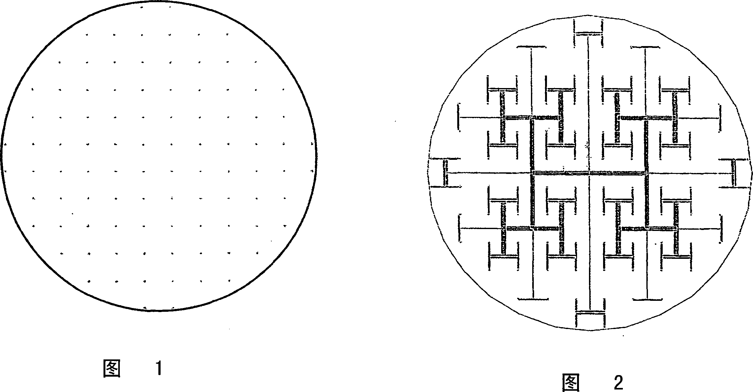
[0030] FIG. 1 shows the side of the liquid distributor or liquid collector facing the cylindrical packing. 96 equidistant openings can be seen, which are evenly arranged on the circular flow cross-section. These openings are circular.
[0031] FIG. 2 shows the side of the liquid distributor or liquid collector with a centrally located inlet or outlet facing away from the cylindrical packing. Symmetrical and asymmetrical T-distributor shaped flow channels are shown here. The openings to the cylindrical packing are in each case in the tip of the T.
Login to View More PUM
 Abstract
The invention relates to a liquid distributor or collector for liquid chromatography columns with a preferably round base. Said liquid distributor or collector is particularly suitable for columns that have a large diameter in relation to the packing height.
Description
technical field [0001] The present application relates to a liquid distributor or liquid collector for liquid chromatography columns, which is especially suitable for columns with a large cross-sectional area compared to the packing height. Background technique [0002] Liquid distributors or liquid collectors are used in column chromatography to distribute or collect liquid evenly over the flow cross-section. This is a necessary prerequisite for achieving the desired separation efficiency. [0003] Development work in chromatography has progressed towards the use of larger column diameters in order to fit within the column the amount of adsorbent required to purify increasingly larger feed volumes, since column length due to pressure Losses and the shortest possible dwell times or processing times are upwardly limited. In order to be able to continue to achieve good separation efficiencies even with these columns, which have a large cross-sectional area compared to the pa...
Claims
Login to View More Application Information
Patent Timeline
 Patent Type & AuthorityApplications(China)
IPC IPC(8): G01N30/60
CPCG01N30/6017Y10T29/494B01D15/14B01D15/18G01N30/02G01N30/6004G01N30/603
InventorG·-H·克勒普S·博克尔J·斯特鲁布H·坎西H·施马勒
Owner日本株式会社维美希