
Liquid dispenser

a dispenser and liquid technology, applied in the field of dispensers, can solve the problems of inconvenient discharging of liquids,

Inactive Publication Date: 2014-08-07
GP STRATEGIES CORPORATION
View PDF6 Cites 2 Cited by
  • Summary
  • Abstract
  • Description
  • Claims
  • Application Information

AI Technical Summary

Benefits of technology

The system enhances accuracy, reduces wait times, minimizes energy consumption, and extends the lifespan of dispenser components by pre-chilling only when needed and using a more efficient, compact design for LNG dispensing.

Problems solved by technology

The existing configuration of LNG dispensers may have certain limitations.
In addition, Coriolis-type flow meters are generally expensive.
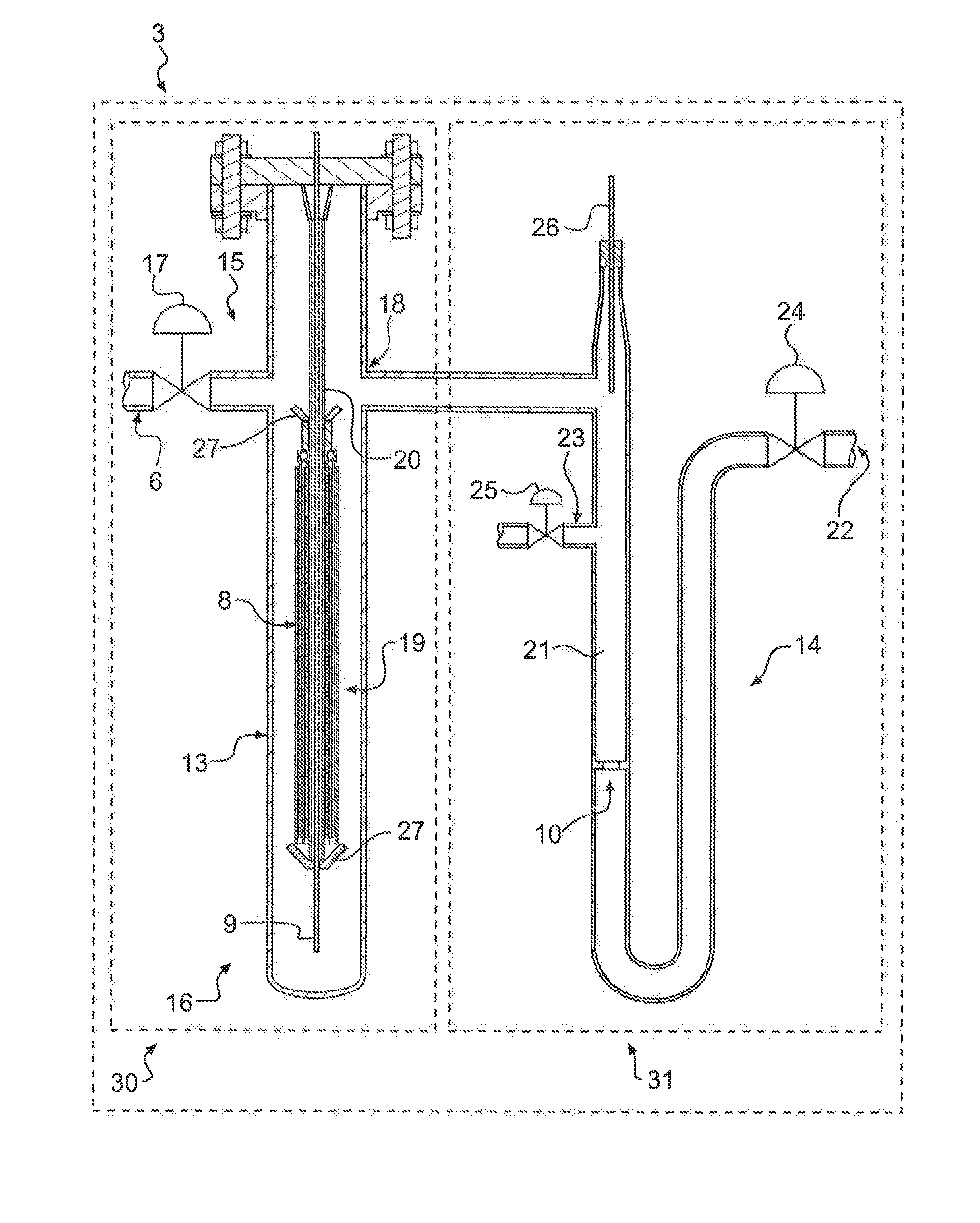
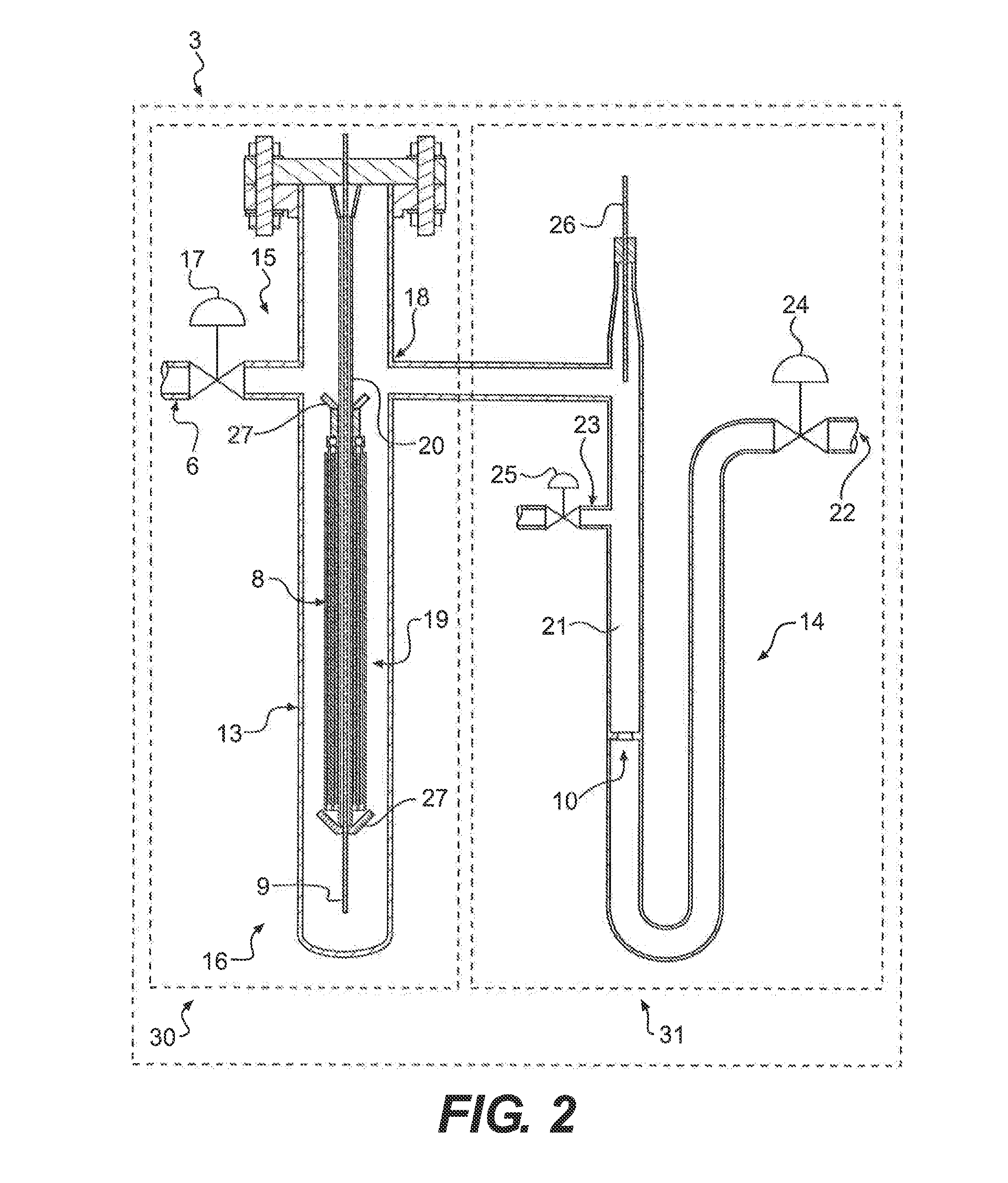
Furthermore, typical LNG dispensers house both the density-measuring device and the volumetric flow-measuring device within the same chamber, which results in an undesirably bulky LNG dispenser.
Additionally, preparing an LNG dispenser for dispensing fuel may take time and may cause undesirable delay for consumers.
Alternatively, maintaining a dispenser in a constant state of readiness for dispensing LNG may consume undue amounts of power and may generate unwanted byproducts, such as heat.
It may also place undue stress on the dispensing system components, which could increase maintenance costs as a result of more frequent repairs and / or more frequent replacement of parts.

Method used


Image

  • Liquid dispenser
  • Liquid dispenser
  • Liquid dispenser

Examples


Embodiment Construction

[0025]Reference will now be made in detail to the exemplary embodiments of the present disclosure described above and illustrated in the accompanying drawings.

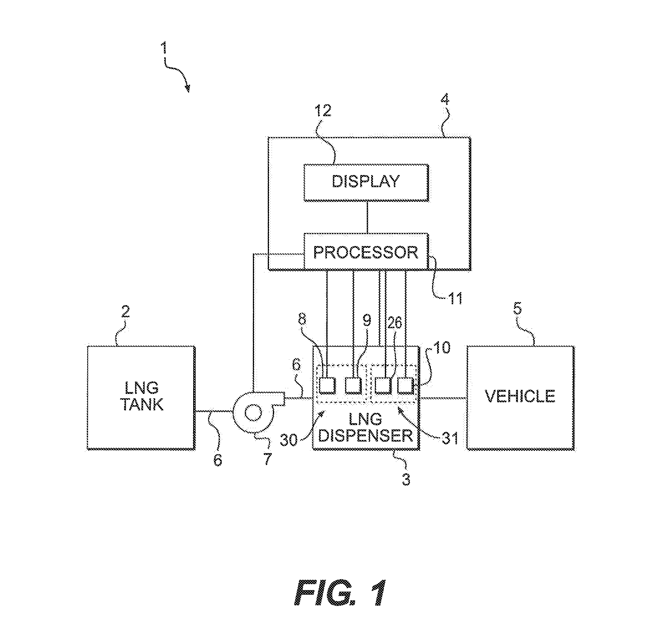
[0026]FIG. 1 illustrates a diagrammatic representation of an LNG dispensing system 1, according to an exemplary embodiment. LNG dispensing system 1 may include an LNG tank 2, an LNG dispenser 3, and a control system 4. LNG dispensing system 1 may be configured to deliver a cryogenic liquid to a use device, such as vehicles, ships, and the like. In the exemplary embodiment of FIG. 1, LNG dispensing system 1 may deliver LNG to a vehicle 5. While the present disclosure will refer to LNG as the liquid to be employed, it should be appreciated that any other liquid may be utilized by the present disclosure. Furthermore, in addition to vehicle 5, any other use device may receive the liquid from LNG dispensing system 1.

[0027]LNG tank 2 may include an insulated bulk storage tank for storing a large volume of LNG. An insulated communica...


PUM


Abstract

Embodiments of the disclosure may include a dispensing system for dispensing a cryogenic fluid. The dispensing system may include a cryogenic fluid dispenser, a pump, and a conduit connecting the pump to the dispenser. The system may also include a processor and a vehicle detection subsystem configured to detect a vehicle. When the vehicle detection subsystem provides to the processor a signal reflecting detection of a vehicle, the processor may initiate a pre-chill operation that prepares at least one of the pump or the dispenser to dispense the cryogenic fluid.

Description

CROSS REFERENCE TO RELATED APPLICATIONS[0001]This patent application is a continuation-in-part of U.S. patent application Ser. No. 13 / 305,102, filed Nov. 28, 2011, which claims the benefit of priority under 35 U.S.C. §§119 and 120 to U.S. Provisional Patent Application No. 61 / 418,679, filed Dec. 1, 2010, both of which are incorporated herein by reference in their entirety.FIELD OF THE DISCLOSURE[0002]Embodiments of the present disclosure include dispensers, and more particularly, dispensers for pre-chilling, dispensing, and metering a liquid, such as liquefied natural gas.BACKGROUND OF THE DISCLOSURE[0003]Generally speaking, liquefied natural gas (LNG) presents a viable fuel alternative to, for example, gasoline and diesel fuel. More specifically, LNG may be utilized as an alternative fuel to power certain vehicles. However, a primary concern in commercializing LNG includes accurately measuring the amount of LNG that is dispensed for use. Particularly, the National Institute of Stan...

Claims


Application Information

Patent Timeline
Patent Type & Authority Applications(United States)
IPC IPC(8): F17C13/02F17C7/02
CPCF17C7/02F17C13/026F17C2201/054F17C2203/03F17C2205/0355F17C2221/033F17C2223/0161F17C2223/033F17C2227/0135F17C2250/032F17C2250/0439F17C2250/0443F17C2250/0495F17C2260/024F17C2265/065F17C2270/0105F17C13/023
Inventor MACKEY, MICHAEL
Owner GP STRATEGIES CORPORATION
Learn More