Magnetic resonance imaging apparatus
A technology of magnetic resonance imaging and equipment, applied in magnetic resonance measurement, measurement using nuclear magnetic resonance image system, measurement of magnetic variables, etc., can solve problems such as difficulty in improving image quality, limitation of imaging area, poor versatility, etc.
- Summary
- Abstract
- Description
- Claims
- Application Information
AI Technical Summary
Problems solved by technology
Method used
Image
Examples
Embodiment approach 1
[0036] Embodiment Mode 1 regarding the present invention is described below.
[0037] (Hardware Configuration)
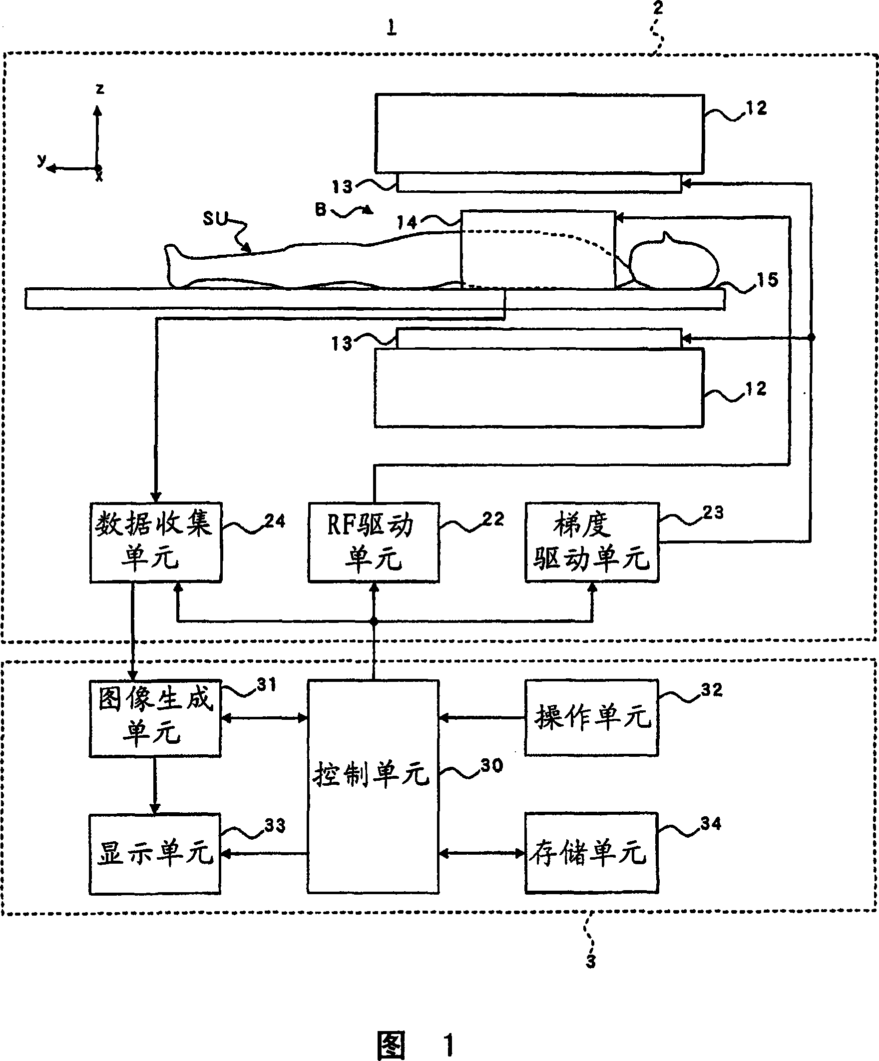
[0038] FIG. 1 is a configuration diagram of a magnetic resonance imaging apparatus 1 in Embodiment 1 of the present invention.
[0039] As shown in FIG. 1 , the magnetic resonance system 1 in this embodiment has a scanning unit 2 and an operating control unit 3 .
[0040] Next, the scanning unit 2 will be explained.
[0041] As shown in FIG. 1 , the scanning unit 2 has a static magnet unit 12 , a gradient coil unit 13 , an RF coil unit 14 , a bracket 15 , an RF drive unit 22 , a gradient drive unit 23 and a data collection unit 24 . The scanning unit 2 transmits RF pulses to the subject SU to excite the spins of the subject SU in the imaging space B, form a static magnetic field in the imaging space B, and perform an imaging sequence IS, wherein the acquisition of The SU transmits RF pulses) transmits gradient pulses to generate magnetic resonance signals in the ...
Embodiment approach
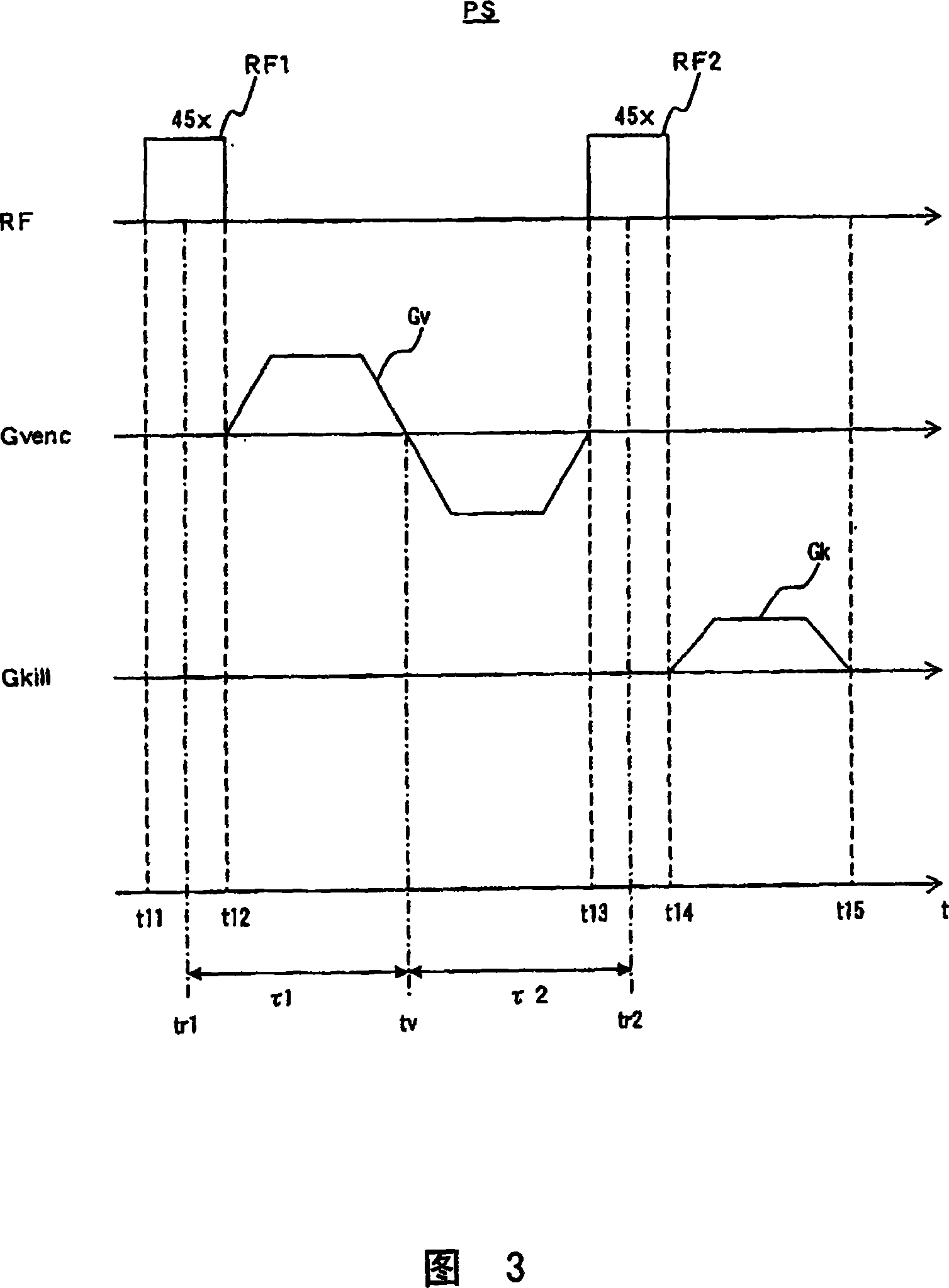
[0074] Here, as shown in FIG. 3 , from the first time point t11 to the second time point t12 , the scanning unit 2 transmits the first RF pulse RF1 , RF1 is a rectangular pulse. In this embodiment, as shown in FIG. 4(A1) and FIG. 4(B1), the magnetization vector points to the magnetostatic direction z in the object SU, and the scanning unit 2 points to the spins S1 and S2 emits a first RF pulse RF1. As shown in Fig. 4(A2) and Fig. 4(B2), the polarization vectors of these spins S1 and S2 are flipped to be along the yz plane.
[0075]More particularly, as shown in FIG. 4(A1) and FIG. 4(B1), the first RF pulse RF1 whose flip angle is 45° and whose phase is in the x direction is transmitted to the spins S1 and S2, the spins S1 and S2 The longitudinal magnetization of is M0, the transverse magnetization is zero, and as shown in Fig. 4(A2) and Fig. 4(B2), the magnetization vectors attributable to the spins S1 and S2 tilt from 0° direction to 45° on the yz plane ° direction.
[0...
Embodiment approach 2
[0109] Next, Embodiment 2 of the present invention will be described.
[0110] This embodiment differs from the most recent embodiment 1 ( FIG. 3 ) in the preparation sequence performed when imaging the subject SU. This mode of implementation is based on a preparation sequence known as the CPMG (Carr-Purcell-Meiboon-Gukk) method, and is similar to Embodiment 1 except in this respect. For this reason, descriptions of the same parts will be omitted.
[0111] FIG. 6 is a pulse sequence diagram of the preparation sequence PS in Embodiment 2 of the present invention.
[0112]In Fig. 6, RF represents the time axis of transmitting RF pulses; Gvenc represents the time axis of transmitting velocity encoding pulses; and Gkill represents the time axis of transmitting suppression pulses, for each case the horizontal axis represents the time t and the vertical axis represents the pulse strength. Here, Gvenc and Gkill are time axes for transmitting gradient pulses, and each time axis is ...
PUM
 Abstract
Description
Claims
Application Information
 - R&D
- Intellectual Property
- Life Sciences
- Materials
- Tech Scout
- Unparalleled Data Quality
- Higher Quality Content
- 60% Fewer Hallucinations
Browse by: Latest US Patents, China's latest patents, Technical Efficacy Thesaurus, Application Domain, Technology Topic, Popular Technical Reports.
© 2025 PatSnap. All rights reserved.Legal|Privacy policy|Modern Slavery Act Transparency Statement|Sitemap|About US| Contact US: help@patsnap.com


