Bridge-type crane control apparatus with rocking-prevention function

An overhead crane and control device technology, applied in the directions of transportation and packaging, load suspending elements, etc., can solve the problems of increasing the structural complexity of the overhead crane, easy wear and tear of the mechanical mechanism, and production safety problems, and achieve a good anti-sway effect. , The effect of low transformation difficulty and low cost

Active Publication Date: 2007-08-29
ABB (CHINA) LTD
View PDF0 Cites 24 Cited by
  • Summary
  • Abstract
  • Description
  • Claims
  • Application Information

AI Technical Summary

Problems solved by technology

However, this method requires the driver of the bridge crane to have rich experience, and it is prone to deviation, causing production safety problems
[0006] Some mechanical methods are also used in the prior art to achieve anti-sway control, which increase the complexity of the structure of the bridge crane and

Method used


Image

  • Bridge-type crane control apparatus with rocking-prevention function
  • Bridge-type crane control apparatus with rocking-prevention function
  • Bridge-type crane control apparatus with rocking-prevention function

Examples


Embodiment Construction

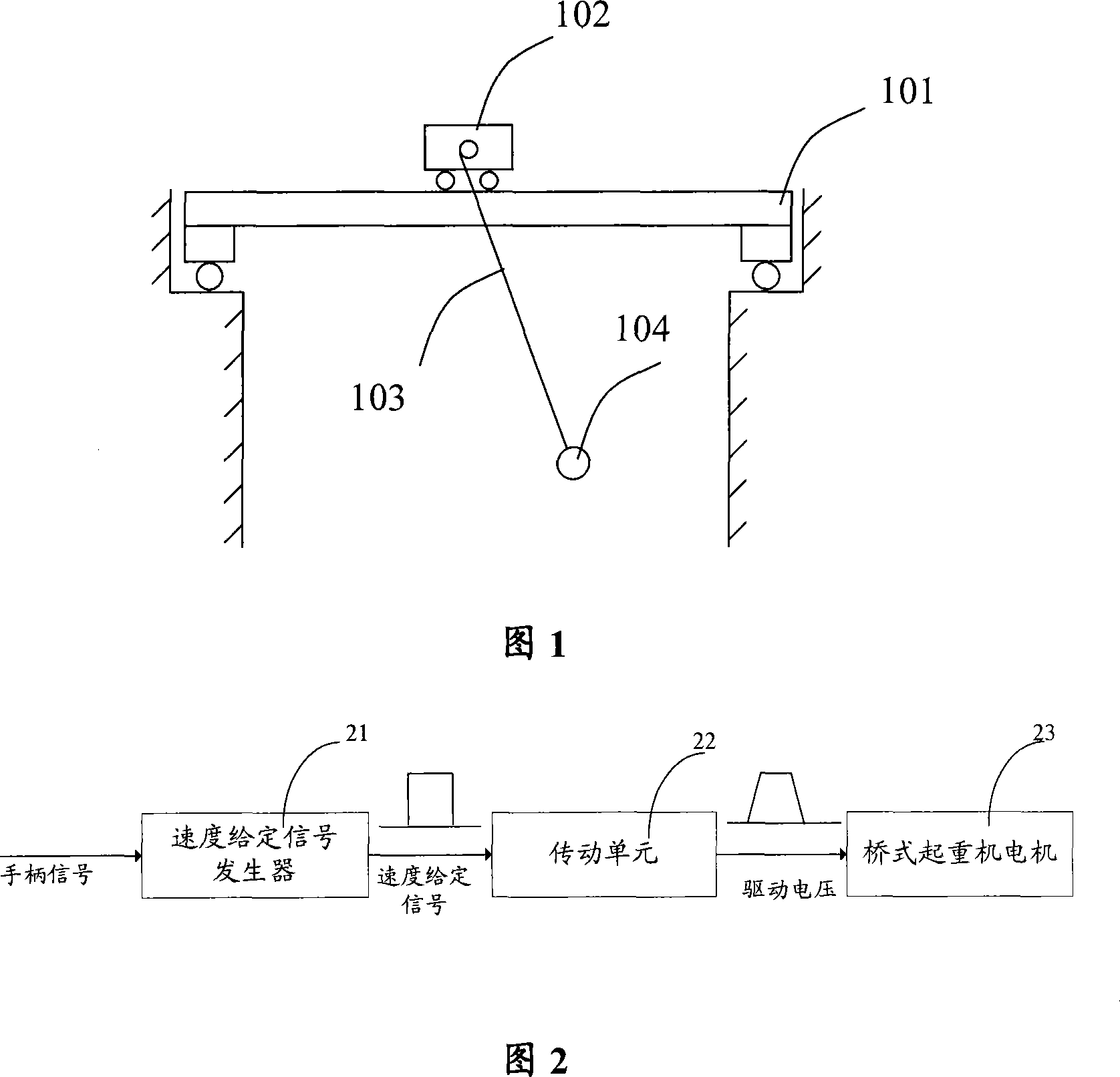
[0041] In the prior art, many bridge cranes have been driven by variable frequency motors as power components. FIG. 2 shows a schematic diagram of the components of the control device of this type of bridge crane.

[0042] As shown in FIG. 2 , the motion control unit of the bridge crane is provided with a speed given signal by a speed given signal generator 21 . The speed given signal generator 21 is generally controlled by the driver of the bridge crane through a control handle. The given speed signal generator 21 generates a corresponding given speed signal according to the manipulation direction and gear position of the handle. The given speed signal is a square wave signal with an amplitude and a time width, and its amplitude represents the required speed value. The square wave signal is directly provided to the speed regulating unit 22, and the speed regulating unit 22 generates a signal to control the bridge crane motor 23 after adding the acceleration and deceleration...


PUM


Abstract

The invention discloses a bridge hoisting control device that has shaking-proof effect. It includes speed giving signal generator, speed adjusting unit and motor, time lag filter that receives the primary value of speed giving signal and transforms into filtered speed giving signal that has shaking-proof effect, and sends to speed adjusting unit. The invention realizes the shaking proof effect for bridge hoist.

Description

technical field [0001] The invention relates to bridge crane technology, in particular to a bridge crane control device with anti-sway function. Background technique [0002] In docks, workshops, warehouses, etc. on industrial sites, bridge cranes are widely used to transport and dispatch heavy goods. Bridge grab ship unloaders, shoreside container cranes, cranes, etc. all belong to the category of bridge cranes. [0003] Taking driving as an example, Figure 1 is a schematic diagram of the basic composition of driving. As can be seen from FIG. 1 , the moving parts of the crane mainly include three parts: a cart 101 , a trolley 102 and a steel rope 103 connected between the trolley 102 and the load 104 . Wherein, the trolley 101 can move forward and backward along the trolley guide rail; the trolley 102 can move left and right along the trolley guide rail on the trolley 101 perpendicular to the running direction of the trolley 101; the steel rope 103 is fixed on the trolley...

Claims


Application Information

Patent Timeline
IPC IPC(8): B66C13/06
Inventor 王晓军
Owner ABB (CHINA) LTD
Why Eureka
Try Eureka