Pump and pumping system

A pump casing and electronic substrate technology, applied in the field of pumps and pump systems, can solve the problems of high-density installation requirements of electronic components that cannot meet the miniaturization requirements of information equipment, increase the area of ​​electronic substrates, abnormal operation and failure, etc. The effect of miniaturization, improvement of installation efficiency, prevention of abnormal operation and failure

Inactive Publication Date: 2007-08-29
SANKYO SEIKI MFG CO LTD
View PDF1 Cites 7 Cited by
  • Summary
  • Abstract
  • Description
  • Claims
  • Application Information

AI Technical Summary

Problems solved by technology

[0007] However, if the pump and the processing circuit including the driver IC are located at a distance from each other, only this will increase the area of ​​the electronic substrate, so it cannot meet the miniaturization requirements of information equipment and the high-density mounting requirements of various electronic components.
[0008] Also, in the way the flexible ribbon and lead wires have been routed from the pump in the past, the electrical signals flowing through them sometimes generated noise on the electronic substrate
At this time, various electronic components may experience abnormal operation and failure

Method used


Image

  • Pump and pumping system
  • Pump and pumping system
  • Pump and pumping system

Examples


Embodiment Construction

[0048] Next, the best mode for carrying out the present invention will be described with reference to the drawings.

[0049] [Mechanical structure]

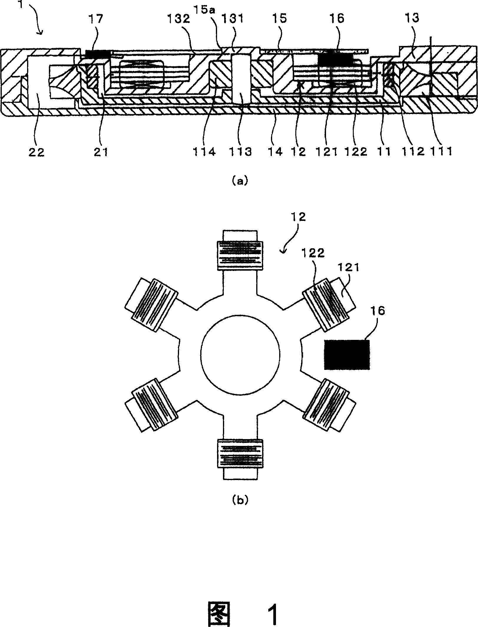
[0050] Fig. 1 is a mechanical configuration diagram showing a pump 1 according to an embodiment of the present invention. In particular, FIG. 1( a ) shows a side sectional view of the pump 1 , and FIG. 1( b ) is a schematic plan view showing the positional relationship between the stator 12 and the drive IC 16 . In addition, for convenience of explanation, Fig. 1(a) is upside down.

[0051]In FIG. 1( a ), the pump 1 according to this embodiment is mainly composed of an impeller 11 , a stator 12 , a pump casing 13 , and a bottom plate 14 .

[0052] A plurality of blades 111 are formed on the outer periphery of the impeller 11 , and the rotation of the impeller 11 induces eddy currents around the blades 111 . In addition, by performing waterproof processing on the surface of the blade 111, it is possible to start the rotation sm...


PUM


Abstract

To provide a pump and pumping system in which the mounting efficiency is improved and which can be controlled without pulling out a flexible tape, etc. from a pump in order to satisfy a demand for smaller information systems and a demand for mounting various kinds of electronic components with high density. A pump comprising an impeller having a plurality of vanes around its outer circumference and a rotor magnet on its inner circumference, a plurality of salient poles positioned opposite to the rotor magnet to radially extend outwardly in the radial direction of the impeller, a pump casing interposed between the rotor magnet and the plurality of salient poles, a driving IC for supplying current to coils wound around the salient poles, and an electronic board on which the driving IC is mounted; wherein the electronic board is fixed to the pump casing while the driving IC is interposed between the plurality of salient poles.

Description

technical field [0001] The invention relates to a pump and a pump system, which are used for the circulation of refrigerant for cooling electronic components and the fuel circulation of a fuel cell, and in particular to a pump and a pump system for improving the installation efficiency. Background technique [0002] In recent years, with the high performance and high functionality of information equipment, the heat generated by the electronic components inside the information equipment has gradually increased, so cooling devices have become more and more important. For example, since the clock frequency of the CPU has greatly improved compared to the past, a method in which a refrigerant is circulated inside to cool the LSI and the like is actually adopted. On the other hand, in recent years, the development of fuel cells is rapidly advancing. This fuel cell is a battery that circulates fuel and extracts electrical energy, and it tends to be more and more miniaturized, and ...

Claims


Application Information

Patent Timeline
Patent Type & Authority Applications(China)
IPC IPC(8): F04D5/00F04D23/00F04D29/42
CPCH02K7/14F04D5/002F04D13/0673F04D29/588H02K11/0073H02K11/33F04D13/0686
Inventor 栗田幸信
Owner SANKYO SEIKI MFG CO LTD
Why Eureka
Try Eureka