Balancing apparatus of inertial force moment
A technology of inertia moment and balancing device, applied in inertia force compensation and other directions, can solve problems such as complex structure, and achieve the effects of reducing noise, eliminating gaps and improving wear and tear.
- Summary
- Abstract
- Description
- Claims
- Application Information
AI Technical Summary
Problems solved by technology
Method used
Image


Examples
Embodiment 1
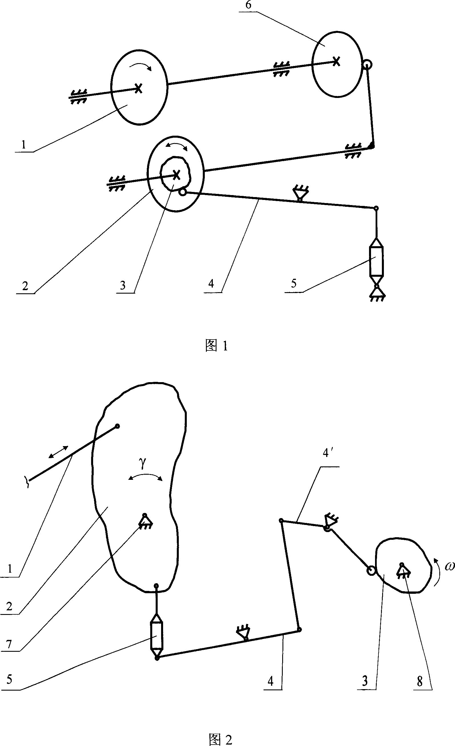
[0021] A kind of moment of inertia balance device as shown in Figure 1, comprises loader 5, connecting rod 4 and program carrier cam 3, described loader 5 and one end of connecting rod 4 that can swing around the middle fulcrum are hinged, connecting rod 4 The other end of the contact with the program carrier cam 3 through the roller, the program carrier cam 3 is installed on the actuator 2, the transmission mechanism 1 controls the movement of the actuator 2 through the cam 6.
[0022] In the figure, the transmission mechanism 1 drives the cam 6 to rotate through the main shaft, and the rotation of the cam 6 drives the actuator 2 to swing through the swing rod, and the actuator 2 generates a moment of inertia when it swings. The other end of the connecting rod 4 relies on the pulling force of the loader 5 to apply pressure through the contact between the roller and the program carrier cam 3. At different contact positions, the program carrier cam 3 has different gyration radii...
Embodiment 2
[0024] As shown in Figure 2, a moment of inertia balance device, the three connecting rods are hingedly connected, the loader 5 is hinged with one end of the connecting rod 4 that can swing around the middle fulcrum, and the other end of the connecting rod 4' is passed through the roller. In contact with the program carrier cam 3 , the loader 5 is fixedly connected with the actuator 2 , and the center of rotation of the program carrier cam 3 is provided with a power shaft 8 for rotating the program carrier cam 3 . The transmission mechanism 1 drives the actuator 2 to swing around the center of rotation 7, and the moment of inertia is generated when the actuator 2 swings. The program carrier cam 3 controls the loader 5 to generate different pulling forces according to different gyration radii, and produces alternating balance on the actuator 2. The torque can be balanced with the moment of inertia generated by the actuator 2 in every phase of the motion cycle. Since the program...
Embodiment 3
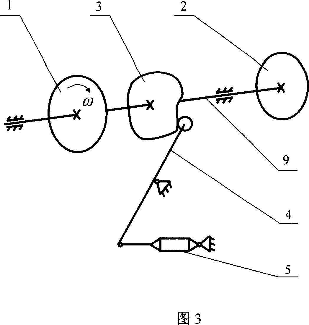
[0033] As shown in Figure 3, a moment of inertia balance device, the transmission mechanism 1 and the actuator 2 are fixedly installed on the main shaft 9, and the program carrier cam 3 between the transmission mechanism 1 and the actuator 2 is fixedly installed on the main shaft 9, which can rotate around One end of the connecting rod 4 swinging at the middle fulcrum is hinged with the loader 5, and the other end of the connecting rod 4 is in contact with the program carrier cam 3 through a roller.
[0034] The transmission mechanism 1 drives the main shaft 9 to rotate, and the main shaft 9 drives the actuator 2 and the program carrier cam 3 to rotate. The loader 5 generates tension and exerts pressure on the program carrier cam 3 through the connecting rod 4, thereby generating a certain balance moment on the main shaft 9. Since the program carrier cam 3 and the rollers have different gyration radii at different contact positions, the loader 5 to produce different magnitudes...
PUM
 Abstract
Description
Claims
Application Information
 - R&D Engineer
- R&D Manager
- IP Professional
- Industry Leading Data Capabilities
- Powerful AI technology
- Patent DNA Extraction
Browse by: Latest US Patents, China's latest patents, Technical Efficacy Thesaurus, Application Domain, Technology Topic.
© 2024 PatSnap. All rights reserved.Legal|Privacy policy|Modern Slavery Act Transparency Statement|Sitemap