

Projector
A technology of projectors and driving parts, applied in the field of projectors, can solve the problems of high noise and poor energy utilization efficiency, and achieve the effects of reducing noise, excellent energy efficiency, and suppressing rotation speed
- Summary
- Abstract
- Description
- Claims
- Application Information
AI Technical Summary
Problems solved by technology
Method used
Image

Examples
Embodiment approach 1
[0075] Outline Structure of a Projector
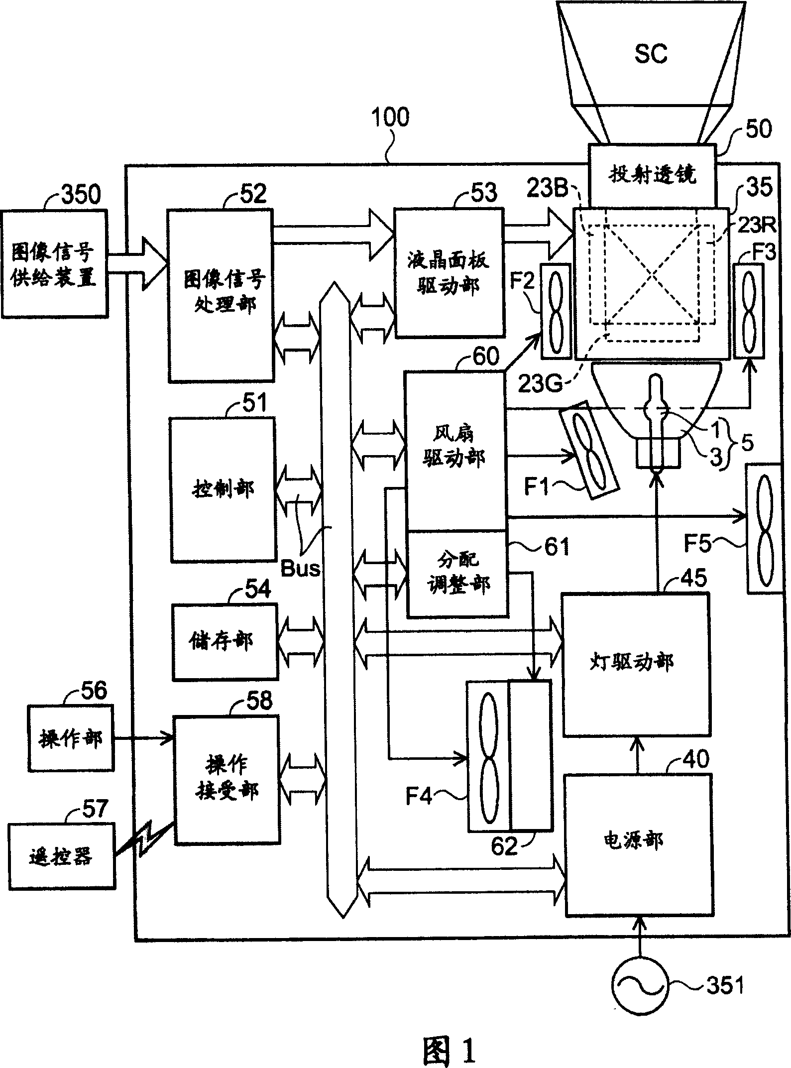
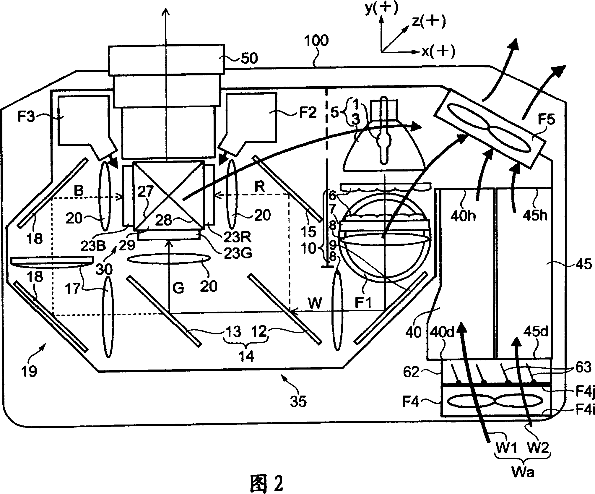
[0076] FIG. 1 is a schematic configuration diagram of a projector according to Embodiment 1 of the present invention. Here, a schematic configuration of the projector 100 will be described. In addition, for comparison, the same parts as those of the conventional projector 200 are described with the same reference numerals.
[0077] The projector 100 separates the light radiated from the light source unit 5 into three primary color components of red light, green light, and blue light, and passes through the liquid crystal light valves 23R, 23G, and 23B for each color light as a light modulation element according to the image signal. A so-called "liquid crystal 3-panel projector" that modulates each color light and magnifies and projects the modulated light of all colors (golden) after recombination on the screen SC through the projection lens 50 . In addition, the liquid crystal light valves 23R, 23G, and 23B are provided as liquid cr...
Embodiment approach 2
[0173] Different forms of distribution part
[0174] Fig. 5(a) and Fig. 6(a) are diagrams showing different configurations of distribution units at the time of low-brightness setting, and Fig. 5(b) and Fig. 6(b) are diagrams showing distribution units at the time of high-brightness setting. Diagrams of different shapes. Here, the different forms of the distribution unit of the projector 100 will be described centering on FIGS. 5(a), (b) and FIGS.
[0175] The R electromagnetic element 72 in Fig. 5(a), (b) is a distributing section different from the distributing section in Embodiment 1, and is a rotary electromagnetic element that adjusts the posture of the fan F4. In addition, in order to distinguish it from the rotary electromagnetic element 65 of the louver 62 of the first embodiment, it is called an R electromagnetic element 72 , and is driven by the distribution adjustment unit 61 .
[0176] The R electromagnetic element 72 is disposed substantially in the lower part of...
Embodiment approach 3
[0195] Different forms of distribution part
[0196] In addition, FIG. 10 is a side view of a different form of a distribution part. Here, different forms of the distribution unit of the projector 100 will be described with reference to FIG. 10 . In addition, FIG. 10 has seen the fan F4 from the suction surface F4i side.
[0197] The partition plate 92 in FIG. 10 is a distributing unit in a different form from the distributing unit in Embodiment 1 and the above-mentioned R electromagnetic element 72 and linear actuator 82, and is provided between the lamp driving unit 45, the power supply unit 40, and the fan F4. , that is, the air supply side F4j side. Moreover, the opening part 93 of substantially the same size as the blowing surface F4j of the fan F4 is formed in the substantially center part of the partition plate 92. As shown in FIG.
[0198] Next to the partition 92 , a linear actuator (not shown) is disposed, and the telescopic shaft of the linear actuator is attache...
PUM
 Abstract
Description
Claims
Application Information