Contactless power transfer system

A power transmission, non-contact technology used in electromagnetic wave systems, radiation diagnostic data transmission, circuits, etc., to solve problems such as maintenance interference, increased system weight, volume and complexity, and reduced reliability.

Active Publication Date: 2007-08-29
GENERAL ELECTRIC CO
View PDF0 Cites 45 Cited by
  • Summary
  • Abstract
  • Description
  • Claims
  • Application Information

AI Technical Summary

Problems solved by technology

[0005] However, scanning systems based on rotating gantry have proven to have certain disadvantages
High voltage cabinets and inverters on the rotating gantry section add weight, bulk and complexity to the system
Further, brush and slip ring mechanisms, which are typically used to carry appreciable currents, lead to reduced reliability, maintenance problems, and the generation of electrical noise that interferes with sensitive electronics

Method used


Image

  • Contactless power transfer system
  • Contactless power transfer system
  • Contactless power transfer system

Examples


Embodiment Construction

[0023] The terms "low pressure" and "high pressure" used throughout do not represent absolute values, but merely refer to a relative relationship to each other.

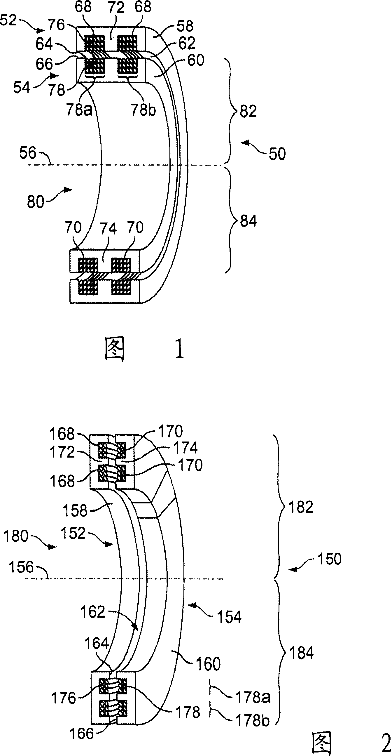
[0024] Figure 1 shows a contactless power transfer system 50 formed in accordance with one embodiment of the present invention. The system 50 includes a stationary part 52 and a rotating part 54 which are proximate to each other and arranged concentrically about an axis 56 . The rotating component 54 rotates around the axis 56 relative to the fixed component 52 . By way of example, the stationary part 52 may simply represent a stator, while the rotating part 54 may represent a rotor, both of which may be coupled to the same frame, such as a platform (eg, see Figures 10 and 12). The fixed part 52 has a fixed iron core 58 , while the rotating part 54 has a rotating iron core 60 . The stationary core 58 and the rotating core 60 have respective inner surfaces 64 and outer surfaces 66 . Inner surface 64 and outer surfa...


PUM


Abstract

In accordance with one embodiment, a contactless power transfer system is provided that comprises a stationary member including a power input configured to receive power at first voltage from a power supply. The system further includes a rotating member rotatably coupled to the stationary member and a rotary transformer. The rotary transformer has primary and secondary sides, with the primary side being disposed on the stationary member. The primary side has a primary winding that receives power at the first voltage from the power input. The secondary side is disposed on the rotating member and produces power at a second voltage. The secondary side has a rotating core and separate secondary sub-windings, each of which has forward and return paths that are circumferentially disposed about the rotating core. The forward and return paths of each of the sub-windings rotate proximate to, and are disposed a substantially equal distance from, the primary winding disposed on the stationary member.

Description

technical field [0001] Embodiments of the invention relate generally to power transfer mechanisms, and more particularly to contactless power transfer systems. Background technique [0002] High voltage power transformers are used in different applications such as baggage scanning systems, computed tomography (CT) systems, and similar applications. CT systems are often used to obtain non-interventional tomographic images of detection objects, especially internal images of human tissue for medical analysis and treatment. Current baggage scanning systems and CT systems place inspected objects, such as baggage or patients, on a conveyor belt or table within a central aperture of a rotating gantry supported by a fixed gantry. The rotating gantry includes an x-ray source and a detection array on opposite sides of the aperture, both of which rotate around the subject being imaged. At each of several angular positions (also referred to as "projections") along the rotational path,...

Claims


Application Information

Patent Timeline
Patent Type & Authority Applications(China)
IPC IPC(8): H01F38/18H02J17/00A61B6/02G01N23/00
CPCH01F38/18A61B6/032A61B6/56
Inventor J·S·卡查J·R·施米德特
Owner GENERAL ELECTRIC CO
Why Eureka
Try Eureka