Supercharge Your Innovation With Domain-Expert AI Agents!

Optoelectronic yarn sensor assembly

A sensor device, photoelectric technology, applied in the direction of measuring devices, instruments, scientific instruments, etc., can solve problems such as unreliable scanning

Inactive Publication Date: 2007-08-29
IRO AB
View PDF0 Cites 0 Cited by
  • Summary
  • Abstract
  • Description
  • Claims
  • Application Information

AI Technical Summary

Problems solved by technology

Delicate yarn qualities either cannot be reliably scanned or require delicate and time-consuming adjustments of the sensor device estimation process

Method used


Image

  • Optoelectronic yarn sensor assembly
  • Optoelectronic yarn sensor assembly
  • Optoelectronic yarn sensor assembly

Examples


Embodiment Construction

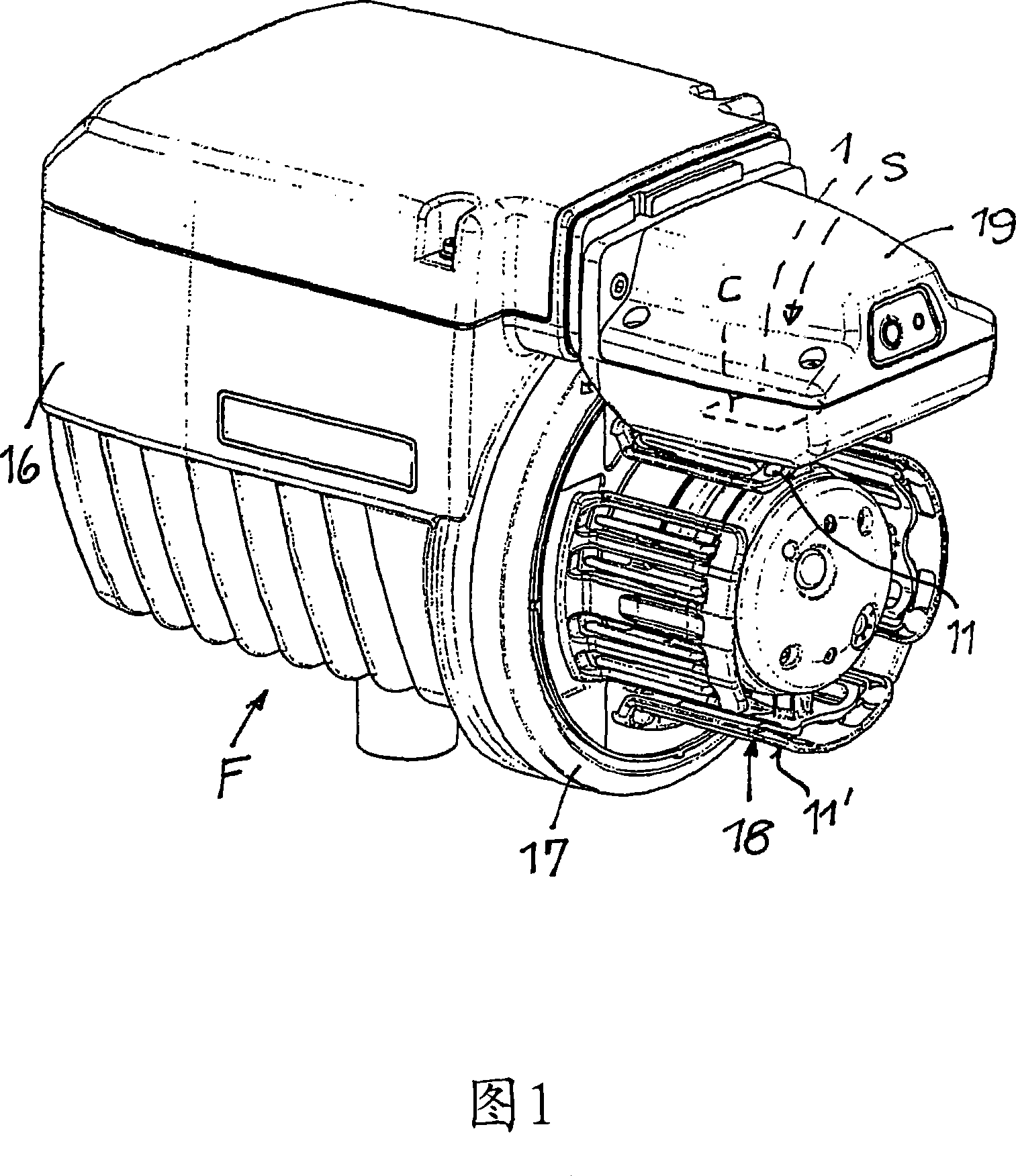
[0028] Figure 1 illustrates a weft yarn storage and measuring yarn feeding device (yarn feeder F) for a not shown jet loom. The yarn feeder F comprises a housing 16, a rotatably driven winding element 17 and a fixed storage body 18 of rod-cage type with several radial adjustment sections 11' (for diameter adjustment). The uppermost part defines a detection area 11 (for example, by a reflector arranged in this part). A casing 19 fixed to the housing 16 contains a not shown braking device for measuring the respective length of weft thread released for each weft picking. Furthermore, the housing 19 contains at least one optoelectronic yarn sensor device S, a housing part 1 covered by a transparent cover C in the vicinity of the detection area 11 .

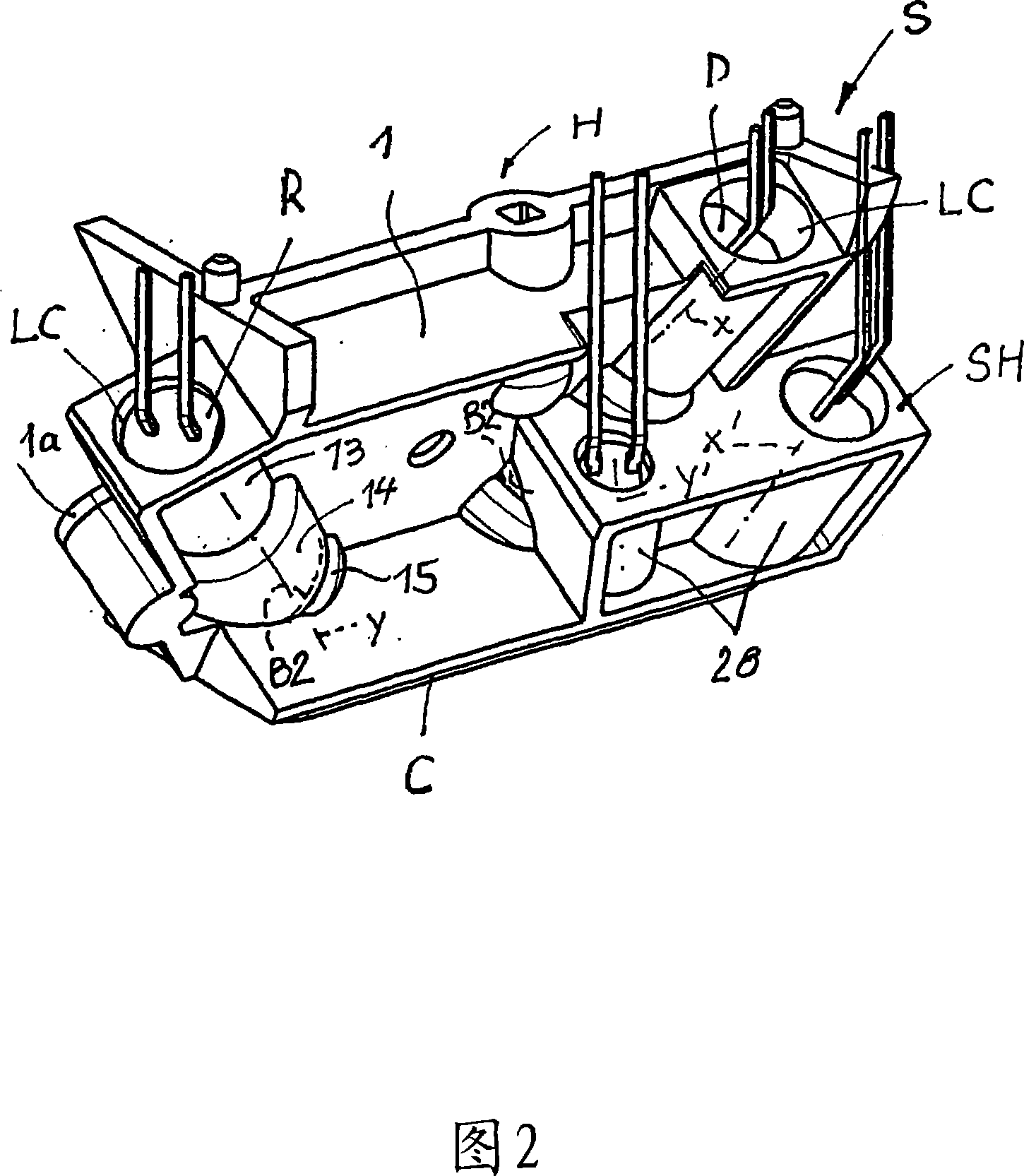
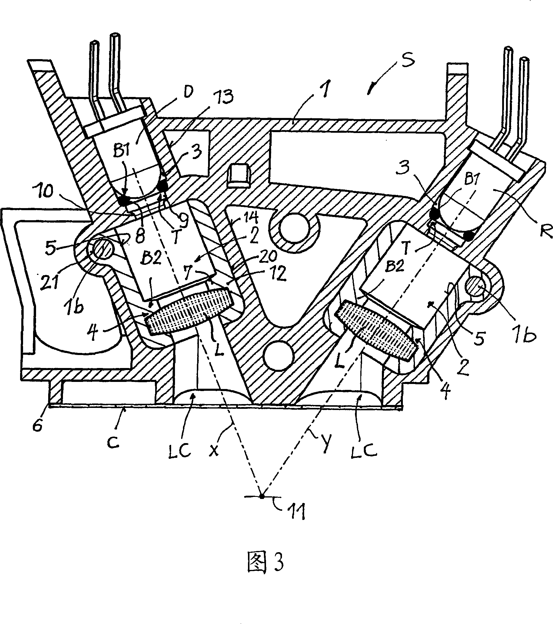
[0029] The photoelectric yarn sensor device S needs to be compact in order to use as little installation space as possible. The sensor device S is connected to an evaluation circuit (not shown) which supplies a signal for a not show...


PUM


Abstract

An optoelectronic yarn sensor assembly (S) for a yarn feeder (F), the assembly comprising a housing (H) with optical axes defining light channels (LC), a positioning socket (3) for a receiving / emitter component (D), (R) and a holding structure (4) for an optical lens (L), at least the inner light channel walls consisting of plastic or metallic material. An inwardly protruding annular light barrier (B1, B2) and / or outwardly recessed annular light trap (T) is provided in each light channel (LC) adjacent to the positioning socket (3) and adjacent to the holding structure (4). A channel section (5) of the light channel extends between opposite annular light barriers and / or light traps. The inner diameter of the channel section (5) is larger than the inner diameter of the respective annular light barrier and / or light trap.

Description

technical field [0001] The invention relates to an optoelectronic yarn sensor device according to the preamble of claim 1 . Background technique [0002] The housings of such photoelectric yarn sensor devices for yarn feeders available on the market usually consist of composite injection molded plastic parts. The transmit / receive component is disposed in a seat at a distance along the optical axis from the optical lens within the positioning structure. Although the plastic material of the housing is dark colored or black (inner black anti-reflection surface), unavoidable light reflections occur during operation of the sensor device, during which light reflections deteriorate the reading of the signal generated by the receiving part. Pick. There are light reflections in the optical channel and, in some cases, a corona effect in the detection area, by means of which undesired reflected light is sent to the receiving part. These undesired light reflections cause electronic n...

Claims


Application Information

Patent Timeline
Patent Type & Authority Applications(China)
IPC IPC(8): B65H51/22D03D47/36G01V
CPCD03D47/367B65H2553/414B65H2553/44G01N21/8915
Inventor 恩佐·丹多洛
Owner IRO AB
Features
  • R&D
  • Intellectual Property
  • Life Sciences
  • Materials
  • Tech Scout
  • Unparalleled Data Quality
  • Higher Quality Content
  • 60% Fewer Hallucinations
Learn More