Igniting device

A technology of circuit devices and ignition pulses, applied in lighting devices, light sources, electrical components, etc., can solve problems such as high inductance

Inactive Publication Date: 2010-10-13
BAG ELECTRONICS GMBH
View PDF5 Cites 0 Cited by
  • Summary
  • Abstract
  • Description
  • Claims
  • Application Information

AI Technical Summary

Problems solved by technology

Generally speaking, the entire ignition operation will last in the range of several seconds, so that especially the ignition transformer has a high inductance, which will have a neg

Method used


Image

  • Igniting device
  • Igniting device
  • Igniting device

Examples


Embodiment Construction

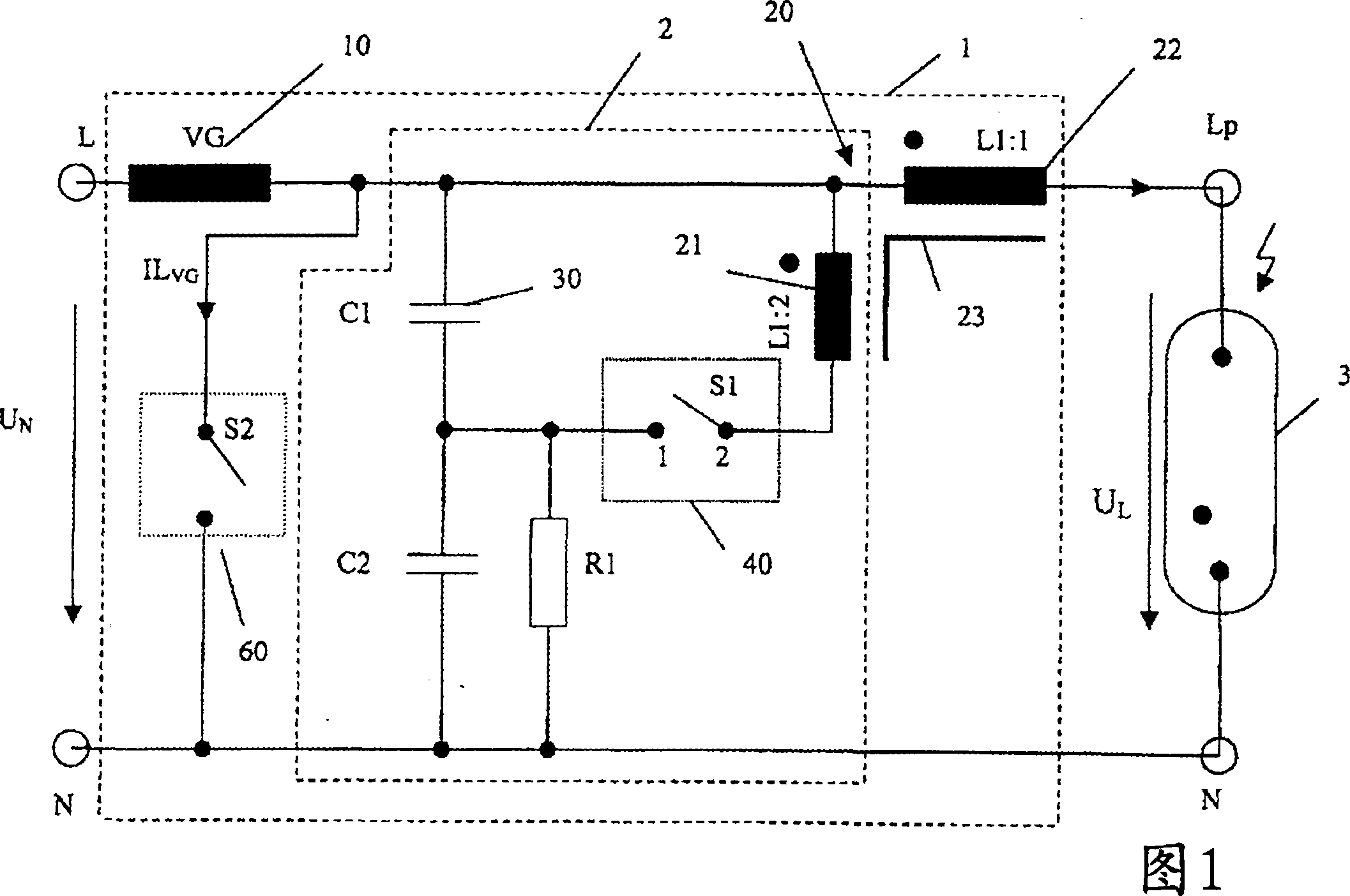
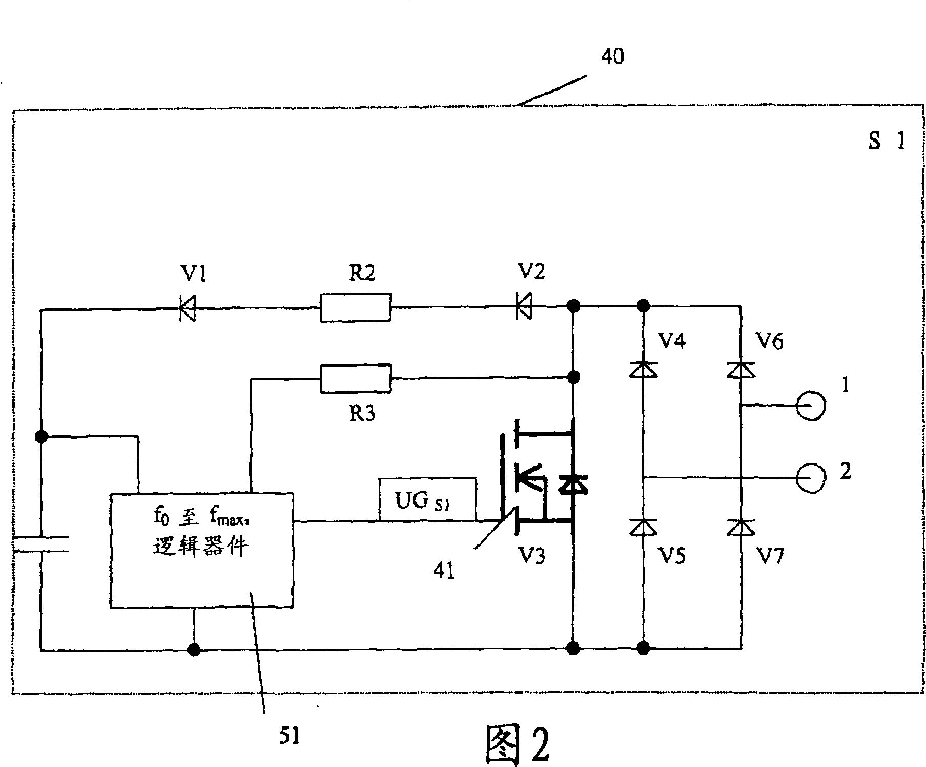
[0033] figure 1 An ignition circuit arrangement 1 according to the invention is shown together with a high-pressure gas discharge lamp 3 to be ignited. Supply voltage U N is applied to the input terminals L, N. The lamp 3 is powered by the lamp choke 10 of a conventional CBD and the secondary side coil winding 22 of the ignition transformer 20 . The ignition trigger circuit 2 includes, as main elements, a surge capacitor 30 chargeable by a parallel circuit composed of a capacitor C2 and a resistor R1, and a primary side coil winding 21 of an ignition transformer 20 . The primary side coil winding 21 is coupled to the secondary side coil winding 22 connected in series with the lamp 3 through an ignition transformer core 23 for transmission and voltage transformation of ignition pulses. A first switching device with an associated controller for triggering the ignition pulse is provided in the trigger circuit 2 , as indicated by reference numeral 40 . Furthermore, the ignitio...


PUM


Abstract

In order to further improve the ignition of gas-discharge lamps, particularly high-pressure gas-discharge lamps, an ignition circuit arrangement is provided for a gas-discharge lamp to which a supply circuit for providing an alternating current supply voltage to the lamp is assigned. The inventive ignition circuit arrangement (1) comprises: an ignition transformer (20) that is connected to a trigger circuit (2) on the primary side and is connected to the lamp (3) on the secondary side for transmitting an ignition pulse; an input power source (30) for the ignition trigger circuit; a first switch means (40) in the trigger circuit, and; control means that control the first switch means. The inventive ignition circuit arrangement is characterized in that for assisting the ignition process in the supply circuit, an energy accumulator (10) that can be controlled by the control means, particularly a voltage source that can be controlled by the control means is arranged in series with regard to the gas-discharge lamp (3). The controllable energy accumulator serves to provide an additional electrical supply during the ignition process over and above the actual alternating current supply ofthe lamp. The invention also relates to a method for igniting a gas-discharge lamp.

Description

technical field [0001] The invention relates to an ignition circuit arrangement for igniting a gas discharge lamp, in particular a high-pressure gas discharge lamp, and to a method for igniting the lamp. Background technique [0002] Especially for high-pressure gas discharge lamps, the ignition voltage required for starting is much higher than the supply voltage for maintaining the discharge. Typically, in the cold start state, an ignition voltage pulse of approximately 1 kV to 5 kV is required for the ignition voltage pulse, depending on the respective lamp used. Due to the pressure increase at high temperatures, much higher ignition voltages are required for thermal ignition of high-pressure gas discharge lamps, which lie in the order of 10 to 60 k, depending on the respective material to be ionized and the power of the lamp used. within the volt range. [0003] Conventional high-voltage ignition devices for high-pressure gas discharge lamps are usually designed in the ...

Claims


Application Information

Patent Timeline
IPC IPC(8): H05B41/04
CPCH05B41/2881Y02B20/204H05B41/042Y02B20/00
Inventor 费迪南德·梅尔藤斯赖因哈德·施奥尔特托拜厄斯·施尔特
Owner BAG ELECTRONICS GMBH
Why Eureka
Try Eureka