Apparatus and method for measuring rotation-axis speed by impulse

A technology of rotating shaft and rotating speed, which is applied in the field of devices that use pulses to measure the rotating speed of rotating shaft, can solve the problems of large error and frequency effect caused by interruption, and achieve the effect of reducing the error and increasing the measurement range.

Inactive Publication Date: 2007-09-05
WEIHAISHIWEILI TOP GRADE TOOL CO
View PDF0 Cites 15 Cited by
  • Summary
  • Abstract
  • Description
  • Claims
  • Application Information

AI Technical Summary

Problems solved by technology

However, in some mechatronics systems, the rotational speed of the rotating shaft varies greatly, which causes the frequency of the rotational speed pulse signal to vary greatly. If the frequency measurement method is used, the error will be large when the rotational speed is low; It is usually n

Method used


Image

  • Apparatus and method for measuring rotation-axis speed by impulse
  • Apparatus and method for measuring rotation-axis speed by impulse
  • Apparatus and method for measuring rotation-axis speed by impulse

Examples


Embodiment Construction

[0028] The present invention will be further described below in conjunction with the accompanying drawings and embodiments.

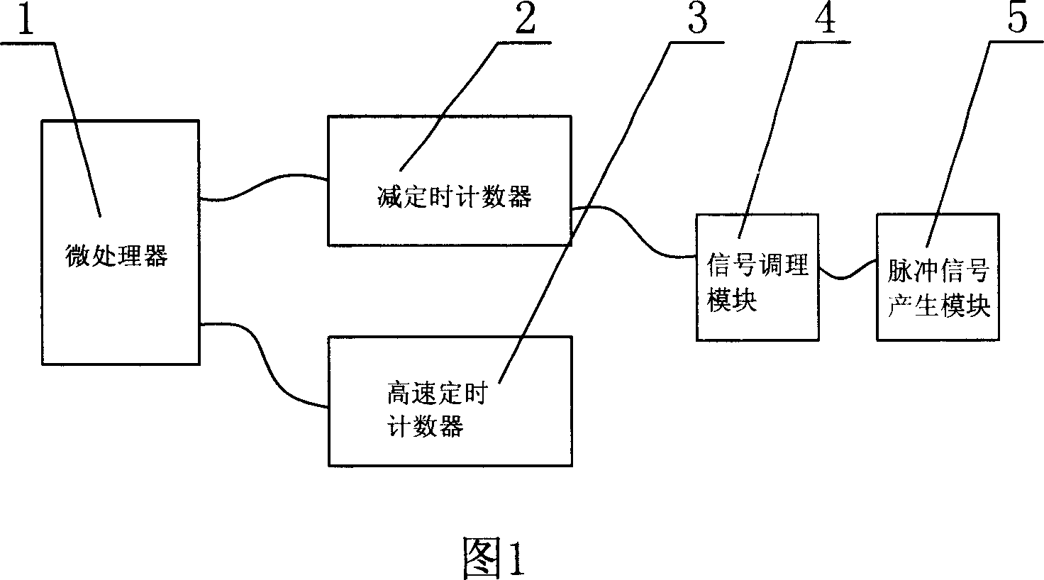
[0029] As shown in Figure 1: device of the present invention comprises microprocessor 1, high-speed timing counter 3, pulse signal generation module 5, signal conditioning module 4, pulse signal generation module 5 output terminals are connected with signal conditioning module 4 input ends, microprocessor 1 is connected with the high-speed timer counter 3, and it is characterized in that: the microprocessor 1 is also connected with a decrement timer counter 2, and the decrement timer counter 2 is also connected with the output terminal of the signal conditioning module 4.

[0030] During the detection process, the gear rotation on the rotating shaft causes the pulse signal generation module 5 to generate pulses, and then the signal conditioning module 4 forms a square wave and then inputs it into the countdown timer counter 2, and the microprocessor 1 re...


PUM


Abstract

A device of utilizing pulse to measure rotary speed of rotary shaft is prepared as connecting output end of pulse signal generating module to input end of signal regulating module, connecting microprocessor to high speed timing counter and also to a backward-timing counter being connected to output end of signal regulating module.

Description

Technical field [0001] The invention relates to a device for measuring a rotating speed and a method for using the device to measure a rotating speed, in particular to a device and a method for measuring a rotating shaft using pulses. Background technique [0002] With the continuous advancement of technology, modern mechatronics systems need to measure the rotational speed of each rotating shaft and then perform corresponding control according to the measurement results. [0003] The easiest way to measure the rotational speed of the rotating shaft is to use a gear speed sensor to measure the rotational speed of the gear on the rotating shaft. When the gear rotates, the output of the sensor changes as the distance between the top of the tooth, the backlash of the gear and the sensor changes, and the output signal of the sensor is shaped into a square wave signal. When the gear rotates a tooth, it outputs a cycle square wave. There are mainly two detection methods for this...

Claims


Application Information

Patent Timeline
IPC IPC(8): G01P3/481
Inventor 李洪斌
Owner WEIHAISHIWEILI TOP GRADE TOOL CO
Why Eureka
Try Eureka