Flat stacking type propulsion device

A propulsion device, a technology of flat push, applied in the direction of non-rotating propulsion elements, etc., can solve the problems of time-consuming and troublesome turning, unstable operation, large shape resistance, etc., and achieve the effect of large thrust, stable operation and small running resistance

Inactive Publication Date: 2007-09-12
凌广有
View PDF0 Cites 5 Cited by
  • Summary
  • Abstract
  • Description
  • Claims
  • Application Information

AI Technical Summary

Problems solved by technology

[0004] Although ship transportation has the characteristics of large transportation capacity, strong endurance and good economy, most conventional ships use propeller propulsion devices, which have small thrust, large shape resistance (head-on resistance and vortex resistance), slow speed, unstable operation, and time-consuming U-turn. It is troublesome, and the draft is relatively deep, which cannot fully meet the needs of modern water transportation.

Method used


Image

  • Flat stacking type propulsion device
  • Flat stacking type propulsion device
  • Flat stacking type propulsion device

Examples


Embodiment 1

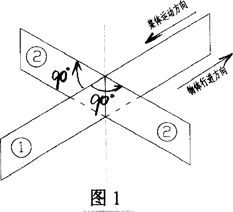
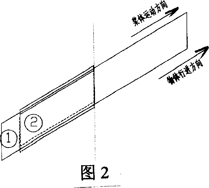
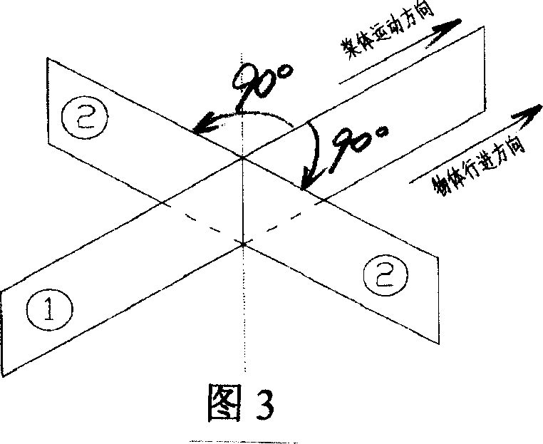
[0012] Embodiment 1: Referring to Figure 5, the propulsion device of this embodiment adopts a single-side paddle type, and the paddle is installed on the lower side of the paddle body, and the paddle can rotate freely forward and backward in a limited manner with the joint part of the paddle body as the axis, and rotate forward The blade is opened, the blade surface is perpendicular to the paddle body, and the blade is folded backwards, and the blade surface is attached to the paddle body; the propulsion device is installed at the bottom of the propelled object, and the paddle body is connected with the power device through the transmission device, and the power device drives the paddle The body reciprocates back and forth on a fixed track. When the paddle body moves forward, the blade is folded backward under the action of water resistance, and the blade surface is attached to the paddle body, forming the minimum cross-section against the water in the forward direction, and mov...

Embodiment 2

[0013] Embodiment 2: Referring to FIG. 6, the difference between this embodiment and Embodiment 1 is that the propulsion device adopts a double-sided blade type, and the blades are symmetrically installed on both sides of the paddle body, and the paddle body is connected with the power device through a transmission device. The power device drives the paddle to reciprocate back and forth on the track, and drives the paddle to repeatedly push the water backwards, thereby pushing the object forward.

Embodiment 3

[0014] Embodiment 3: Referring to FIG. 7, the difference between this embodiment and Embodiment 1 is that the propulsion device adopts an alternate water pushing type, and the blades are divided into two groups, which are respectively installed on two paddle bodies, and the two paddle bodies They are respectively connected to the power device through two transmission devices. When the power device drives one paddle body to move forward, the other paddle body moves backward, thus driving one set of paddles to open and push water, while the other set of paddles is folded state, the two sets of paddles alternately push the water, thereby pushing the object forward.

[0015] Changing the opening direction of the blades, the propulsion devices of the above embodiments 1, 2, and 3 can all realize deceleration, stop or reverse travel, and can solve the problems existing in the propeller propulsion devices of the prior art. Compared with the propeller propulsion devices, the flat The ...


PUM


Abstract

The present invention relates to one kind of propulsion unit and belongs to the field of propulsion technology. The propulsion unit includes one oar body and oar blades mounted on the oar body. The oar blade can rotate freely in limited range around the joint site with the oar body, and is opened to vertical state to the oar body during rotating forward and is folded to contact with the oar body during rotating backward. The oar body is connected to the power device via a driving device so as to reciprocate back and forth and drive the oar blades to push water backwards for the boat to go forward. Changing the oar blade opening direction can realize deceleration, stopping or retrogression. The present invention has the advantages of small resistance, great propulsion force, etc and may be used widely.

Description

1. Technical field [0001] The invention relates to a propulsion device and belongs to the technical field of propulsion. 2. Background technology [0002] The ocean accounts for 71% of the global area, 60% of the world's major cities are located on the coast or within 50km from the coast, and most inland cities are located along the river. About two-thirds of the world's population lives within 80km of the coast. The impact and role played by oceans and rivers on the development of human civilization is indescribable. [0003] The load capacity of water transport is unmatched by other modes of transport. Whether it is sea transport or inland river transport, it is larger than land transport or air transport. In modern world trade, ship transport carries 85% of the cargo volume. Ship transportation can save energy. Calculated by converting the fuel consumed by 1km per ton of cargo into standard coal, the ship transportation is 2kg, the train is 12kg, the automobile is 40kg, ...

Claims


Application Information

Patent Timeline
Patent Type & Authority Applications(China)
IPC IPC(8): B63H1/30
Inventor 凌广有
Owner 凌广有
Why Eureka
Try Eureka