Friction coupling

A friction clutch and friction surface technology, applied in the direction of friction clutch, clutch, mechanical drive clutch, etc., can solve the problems of high manufacturing cost and installation cost, and achieve the effect of small disengagement stroke loss, guaranteed operation reliability, and small disengagement force.

Inactive Publication Date: 2007-09-12
ZF FRIEDRICHSHAFEN AG
View PDF2 Cites 11 Cited by
  • Summary
  • Abstract
  • Description
  • Claims
  • Application Information

AI Technical Summary

Problems solved by technology

[0005] The disadvantage of this solution is that a large number of components must be arranged in a narrow space, which results in correspondingly high manufacturing and installation costs

Method used


Image

  • Friction coupling
  • Friction coupling
  • Friction coupling

Examples


Embodiment Construction

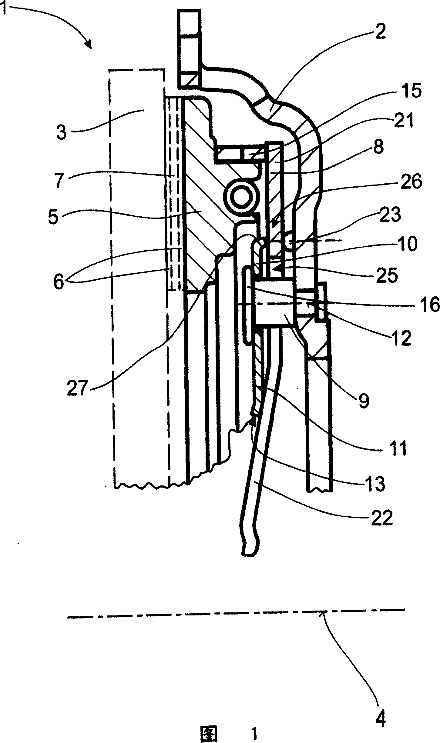
[0060] FIG. 1 shows a conventionally constructed friction clutch 1 . Housing 2 is connected in a rotationally fixed manner to a flywheel 3 (shown in dashed lines) of the internal combustion engine, housing 2 being rotatable about a common axis of rotation 4 . Alternatively, a dual-mass flywheel can also be provided as flywheel 3 , as is shown, for example, in DE 139 39 030 A1 or in DE 19820 503 A1. A pressure plate 5 is arranged in the housing 2 in a rotationally fixed manner but axially displaceable, which pressure plate 5 has a wear compensation device 15 in the exemplary embodiment shown here. A clutch disc 7 (not shown) with a friction lining 6 is arranged between the pressure plate 5 and the flywheel 3 . In this case, the friction lining 6 has a friction surface 6 which cooperates with a corresponding counter-friction surface on the flywheel 3 and on the pressure plate 5 in the engaged state for the transmission of torque. A diaphragm spring 8 is arranged between the pr...


PUM


Abstract

Friction clutch, with a housing; a pressure plate that is not relatively rotatable but axially displaceable in the housing; a clutch plate with at least one friction lining between the pressure plate and the friction surface of the flywheel; a diaphragm spring, It has an actuating tongue formed on it, the diaphragm spring can act on the pressure plate with a pressing force that loads the lining lining and is supported on a bearing area formed on the housing; , directly or indirectly positions the diaphragm spring relative to the housing, passes through the passage region of the actuating tongue and is mounted radially inwardly, wherein a support element with a bearing section is provided, the diaphragm spring during disengagement Supported on this support section, wherein the support element is fixed by the holding element relative to the diaphragm spring and bears against the diaphragm spring with the support section under pretension and has a projection extending radially inwardly of the holding element , these protrusions are supported on the operating tongue.

Description

technical field [0001] The invention relates to a friction clutch, in particular for motor vehicles, which has a housing which is rotationally connected to a flywheel about a common axis of rotation and to an internal combustion engine; but axially displaceable pressure plate; a clutch plate with at least one friction lining between said pressure plate and the friction surface of said flywheel; a diaphragm spring with An actuating tongue formed thereon for deflecting the diaphragm spring around its support region, which can act on the pressure plate with a pressure for applying a load to the friction lining lining force and is supported on a support area configured on the housing; extending from the housing, directly or indirectly positioning the diaphragm spring relative to the housing, passing through the operating tongue and a retaining element mounted radially inside; a support element with a bearing section on which the diaphragm spring rests during disengagement, wherei...

Claims


Application Information

Patent Timeline
Patent Type & Authority Applications(China)
IPC IPC(8): F16D13/71
CPCF16D13/583F16D13/585
Inventor A·林克G·罗尔W·克诺尔
Owner ZF FRIEDRICHSHAFEN AG
Why Eureka
Try Eureka