Straight-through current transformer capable of conveniently taking voltage

A current transformer and feedthrough technology, applied in the field of transformers, can solve the problems of not easy to prevent electricity theft, complex structure and high cost, and achieve the effects of saving labor time, safe operation and low cost

Inactive Publication Date: 2007-09-12
HUBEI SHENGJIA ELECTRIC EQUIP
View PDF1 Cites 4 Cited by
  • Summary
  • Abstract
  • Description
  • Claims
  • Application Information

AI Technical Summary

Problems solved by technology

[0005] Aiming at the disadvantages of existing through-hole current transformers, such as complex structure, high cost and low efficiency, and not easy to prevent electricity theft, the present invention provides a current transformer, which fixes the voltage-taking signal line inside the current transformer, Through the innovative design of the structure of the existing current transformer, the purpose of convenient voltage extraction and effective prevention of electricity theft can be better achieved

Method used


Image

  • Straight-through current transformer capable of conveniently taking voltage
  • Straight-through current transformer capable of conveniently taking voltage
  • Straight-through current transformer capable of conveniently taking voltage

Examples


Embodiment 1

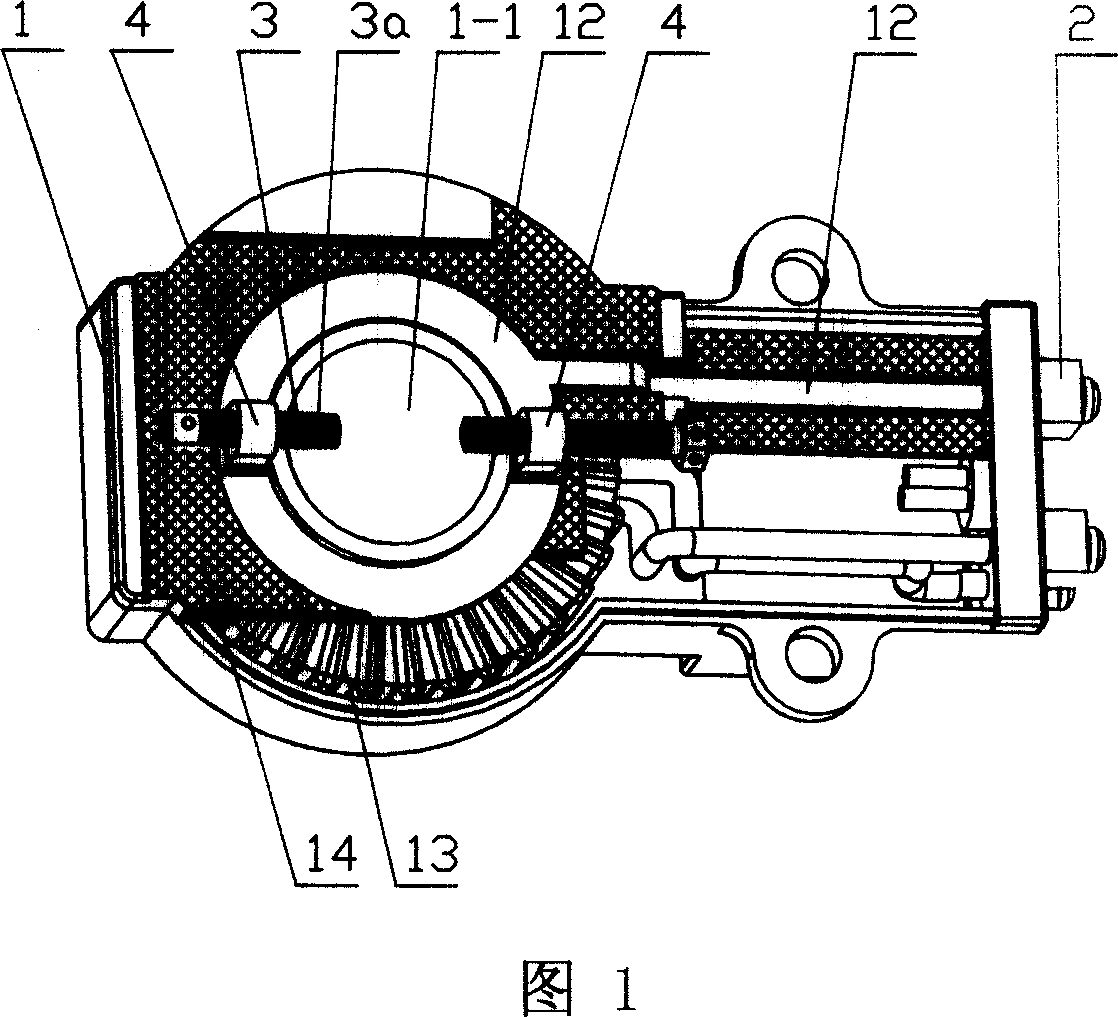
[0053] The current transformer described in this embodiment is mainly used in the case of taking voltage from a bare metal bar. It includes a transformer body 1 with a through hole 1-1. The transformer body 1 is provided with a voltage line outlet terminal 2 that is electrically connected to each other and a voltage-taking component 3. The voltage-taking component 3 is arranged on the through-center One side of the hole 1-1, and the voltage-taking component 3 can move radially along the through hole 1-1.

[0054] Setting the voltage-taking part 3 on one side of the through-hole can prevent the voltage-taking part from occupying the position of the through-hole and affecting the use of the transformer. At the same time, the radial movement of the voltage-taking part along the through-hole can make the mutual inductance of this structure The transformer adapts to the needs of buses with different inner diameters and cross-sectional shapes, thus increasing the adaptability of the...

Embodiment 2

[0062] The current transformer described in this embodiment is mainly used in the case of taking voltage from a transformer guide rod. Unless otherwise specified, the structure described in this embodiment is the same as that in Embodiment 1.

[0063] The difference in structure between the current transformer described in this embodiment and the transformer described in Embodiment 1 is that, referring to Fig. 6A, Fig. 6B, Fig. 7 and Fig. 8, it also includes a nut 5, and the nut 5 The side is provided with hole 5-1, and the hole is provided with the internal screw thread that cooperates with metal stud 3a front end.

[0064] When in use, first penetrate the central hole of the transformer into the guide rod 15 of the transformer, then screw the nut 5 on the guide rod 15 of the transformer, and then screw the metal stud 3 threaded with the metal insert 4

[0065] The front end of a is screwed in the threaded hole 5-1 of nut 5 sides. In this way, it can ensure that the transfo...

Embodiment 3

[0070] The difference between this embodiment and Embodiment 1 and Embodiment 2 is that the structure of the transformer also includes a No. 1 anti-theft electricity mask 6, and the difference with the existing structure is that the No. 6 is connected with the surface of the transformer body 1 in a non-detachable manner. It can be seen that the anti-theft mask of this embodiment is fixed on the transformer body, so that the transformer can be used in any position without limitation in the box. The mask is connected to the transformer body in a non-detachable way, that is to say, after the metering department fixes the anti-stealing mask to the transformer, the mask cannot be removed from the transformer without destroying it. Those who can't hide the eyes and ears to steal electricity can greatly increase the degree of protection against electricity theft.

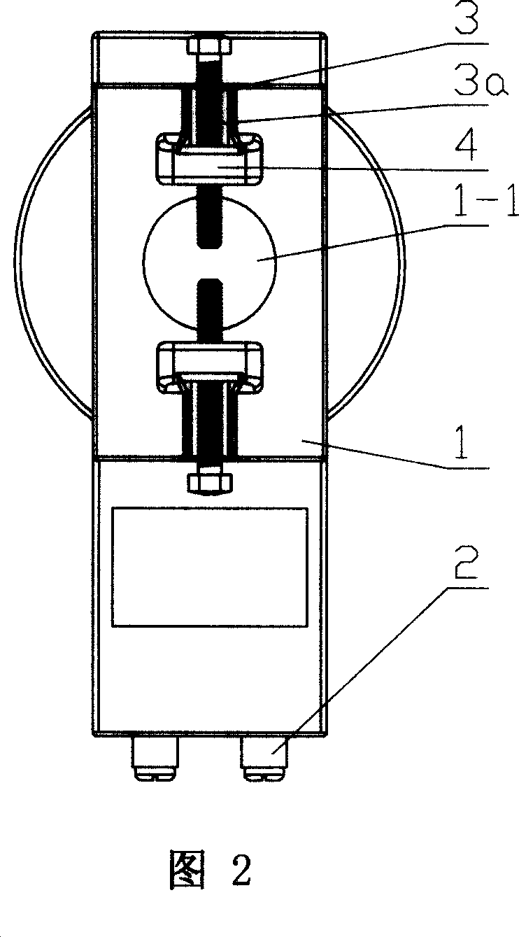
[0071] Figure 2 and Figure 4 clearly show the structure of the outer surface of the transformer body 1, on the basis of...


PUM


Abstract

This invention relates to a straight-through current transformer which can take voltage easily. The invention set voltage-wire leading-out terminal (2) and voltage taking assembly ( 3) on the transformer noumenon ( 1), and each other possess electric interlock relation. The voltage taking assembly set up at one side of whole core (1-1), and can do radial movement follow hole core. This invention use existing metal embeds piece structure of current transformer, directly connect it with pressure-wire leading-out terminal, to realize purpose of taking voltage. the voltage taking mode is shortcut and not easy occur electric larceny, at the same time, the joining between stud and wire is stable.

Description

technical field [0001] The invention relates to a transformer. Background technique [0002] In many feed-through current transformers currently used, there is no voltage signal output, and the voltage signal must be obtained from the corresponding busbar of the transformer. It has the disadvantages of complicated connection lines, high measurement cost and low efficiency, and it is not easy to prevent electricity theft. [0003] Baoding Kaiyu Electric Co., Ltd. has produced a LDF1-0.66 guide rod penetration current transformer, which is a current transformer that can output voltage signals. It is fixed with a central hole on the hollow surface of the core transformer. The metal sheet is provided with a voltage line terminal at the outlet end of the transformer, and the metal sheet is connected to the voltage line outlet terminal inside the transformer. When in use, the center hole of the metal sheet is placed on the guide rod of the transformer, and the transformer is fixe...

Claims


Application Information

Patent Timeline
Patent Type & Authority Applications(China)
IPC IPC(8): G01R15/18
Inventor 万家盛
Owner HUBEI SHENGJIA ELECTRIC EQUIP
Why Eureka
Try Eureka