Method for automatically generating complex components three-dimensional self-adapting finite element grid

An automatic generation, finite element technology, applied in special data processing applications, image data processing, 3D modeling, etc., can solve problems such as inability to generate grids and low grid efficiency, avoid self-intersection and inclusion, improve The effect of solving accuracy and saving judgment time

Inactive Publication Date: 2007-09-12
SHANDONG UNIV OF TECH
View PDF3 Cites 16 Cited by
  • Summary
  • Abstract
  • Description
  • Claims
  • Application Information

AI Technical Summary

Problems solved by technology

[0003] The automatic generation method of the finite element mesh model for the scattered data also has the following disadvantages: (1) cannot generate an adaptive mesh; (2) the efficiency of generating the mesh is low

Method used


Image

  • Method for automatically generating complex components three-dimensional self-adapting finite element grid
  • Method for automatically generating complex components three-dimensional self-adapting finite element grid
  • Method for automatically generating complex components three-dimensional self-adapting finite element grid

Examples


Embodiment

[0021] Embodiment: generate the self-adaptive finite element grid model of motorcycle oil tank, its operation steps are:

[0022] 1. Obtain the surface data of the motorcycle fuel tank with a laser measuring machine, the number of data points is 2211, and use R * -Tree is used as an index structure to establish the topological adjacency relationship of scattered points, and use the pruning strategy to calculate the K nearest neighbors of each data point. Since the data points are evenly distributed, K=10;

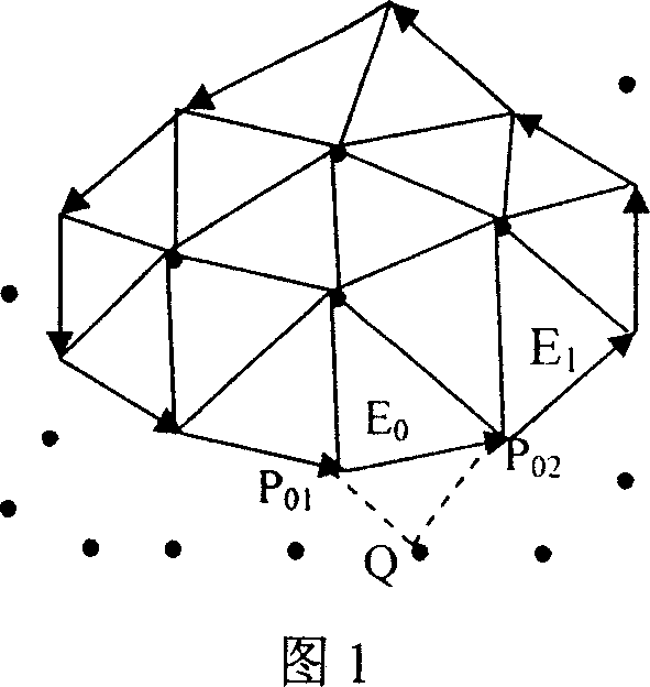
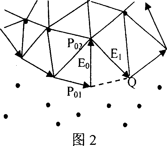
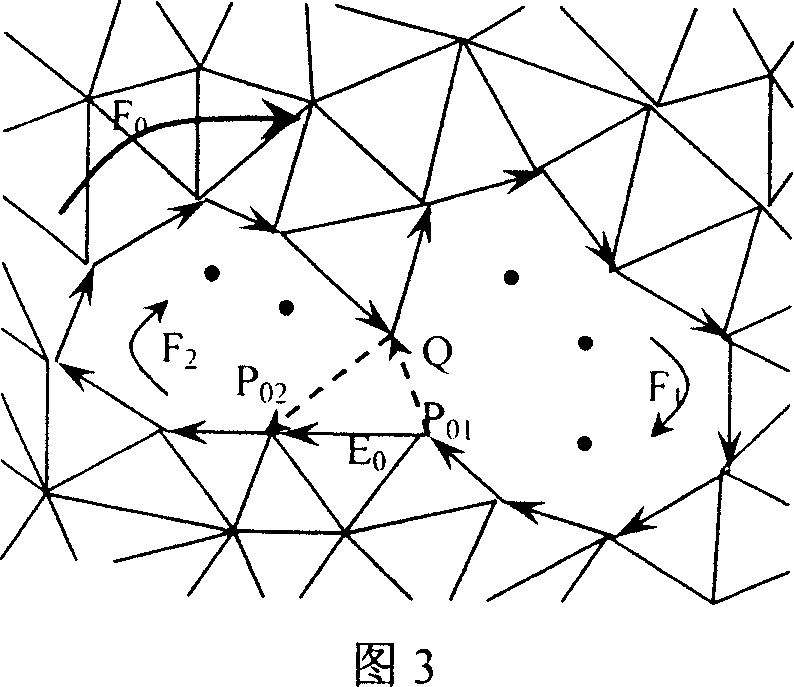
[0023] 2. Among the 2211 measured data, select the data point with the largest Z coordinate and find the two points closest to it in space, then connect these three points into a triangle, adjust the arrangement order of the vertices of the triangle so that the normal vector points to Consistent with the direction of the Z coordinate axis, use the adjusted triangle as the initial wavefront ring and use it as the current wavefront ring

[0024] 3. Define the grid points ins...


PUM


Abstract

The invention provides a method of automatic product complex component triaxiality auto-adapted finite element grid model, its characteristic lies in the step is in turn: (1) gathers the data and carries on the pretreatment; (2) founds the initial wave front ring; (3) defines the saturation point, the freespot, the wavefront side, the wavefront spot, the wavefront two wings and edge flare angle, produces primitive survey data grid model; (4) carries on the auto-adapted encryption to the finite element grid model; (5) optimizes processing. This method while saved the construct time of the finite element grid, produced the grid cell approached to the equilateral triangle, and settles a foundation to enhance the finite element solution precision.

Description

Technical field [0001] The invention provides a method for automatically generating a three-dimensional self-adaptive finite element grid of a complex component, which belongs to the field of computer-aided analysis. Background technique [0002] In the mechanical analysis of complex components, the generation methods of finite element mesh can be divided into two categories: (1) construct the CAD model of complex components, and then discretize the model surface into finite element mesh, refer to Meshkat et al. US Patent No. 4,933,889 and US Patent No. 6,804,635 to Dhondt; (2) Use a laser measuring machine to measure the surface data of the component, and then generate a finite element grid from scattered data points. This method can save complex Under the condition of surface modeling, the finite element mesh is directly generated and the mechanical analysis of the component is realized. Among them, the insertion of finite element grid points is the key step of grid gener...

Claims


Application Information

Patent Timeline
Patent Type & Authority Applications(China)
IPC IPC(8): G06T17/20G06F17/50
Inventor 孙殿柱孙肖霞李延瑞
Owner SHANDONG UNIV OF TECH
Why Eureka
Try Eureka