Check patentability & draft patents in minutes with Patsnap Eureka AI!

Compression indicator

A technology of indicators, compression elements, applied in the direction of instruments, couplings, gaskets, etc., which can solve the problem of not having a quick and easy way to control compression, etc.

Active Publication Date: 2007-09-12
ROXTEC AB
View PDF0 Cites 0 Cited by
  • Summary
  • Abstract
  • Description
  • Claims
  • Application Information

AI Technical Summary

Problems solved by technology

However in this case there is no quick and easy way to control the compression afterwards

Method used


Image

  • Compression indicator
  • Compression indicator
  • Compression indicator

Examples


Embodiment Construction

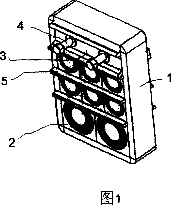
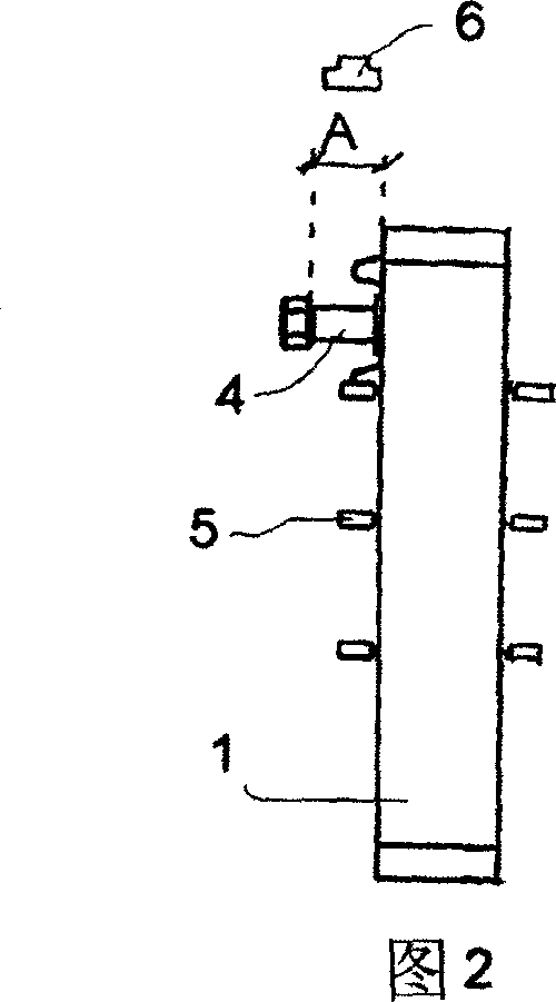
[0014] Figure 1 shows an embodiment of a frame 1 to be placed in openings in walls, roofs, floors or bottoms of houses, boats, electrical cabinets and containers. Walls, roofs, floors, or floors can be generalized to any structure or partition that functions as a boundary. Several modules 2 are arranged within the frame. In each module 2 a cable or pipe can be accommodated. In the embodiment shown, the modules 2 have a plurality of centrally arranged lamellae which can be peeled off so that the opening of each module 2 is sized to the diameter of the cables or pipes contained in the module 2 . Partitions 5 are arranged between modules 2 of different rows. In addition, a compression element 3 , here in the form of a compression wedge, is arranged inside the frame 1 . The compression element 3 has two screws 4 by means of which the dimensions of the compression element 3 can be adjusted. By increasing the size of the element 3 or wedge by the screw 4, the modules 2 will comp...


PUM


Abstract

The present invention concerns a method of control- ling the compression of a compression unit (3) placed in- side a frame (1). It also concerns indicator clips to be 5 used in controlling the compression, which indicator clips may have different designs. In one embodiment the indicator clip (6) has an elongated form with two rounded ends (7). The rounded ends (7) are to be placed on stems of two screws (4) of the compression unit (3). The compression of 10 the compression unit (3) increases with a distance (A) from the screw head of each screw (4) to the compression unit (3). The width of the indicator clip (6) is adapted to said distance (A) at the desired compression.

Description

technical field [0001] The present invention relates to a compression indicator and also to a method of using an indicator clip as a compression indicator. Background technique [0002] This indicator is used in conjunction with compression elements on frames for cable entry, cable transmission or pipe penetrations. These cable entry, cable transmission or pipe penetrations have a modular construction that can be squeezed around a cable or pipe to achieve a tight seal. Typically a plurality of modules are housed within the frame with a compression element for compressing the modules. In addition, partitions are usually provided between modules on different levels within the frame. [0003] Included in the compression element is usually one or more screws or similar elements which are turned to impart the desired compression. Many suppliers of compression elements specify a certain torque so that the screw or similar element can be pushed to achieve the desired compression...

Claims


Application Information

Patent Timeline
Patent Type & Authority Applications(China)
IPC IPC(8): H02G1/00H02G3/00H02G3/22F16L5/00G01L1/00
CPCF16L5/14F16L5/08Y10T29/49236H02G3/22F16L2201/10F16B43/00F16B43/005
Inventor 克里斯特·伦德堡
Owner ROXTEC AB
Features
  • R&D
  • Intellectual Property
  • Life Sciences
  • Materials
  • Tech Scout
  • Unparalleled Data Quality
  • Higher Quality Content
  • 60% Fewer Hallucinations
Learn More