Failure current limit method and device based on the rectifying bridge and bidirectional switch switching
A two-way switch, fault current limiting technology, used in emergency protection circuit devices for limiting overcurrent/overvoltage, circuit devices, usage of superconductor elements, etc. questions of value
- Summary
- Abstract
- Description
- Claims
- Application Information
AI Technical Summary
Problems solved by technology
Method used
Image
Examples
Embodiment 1
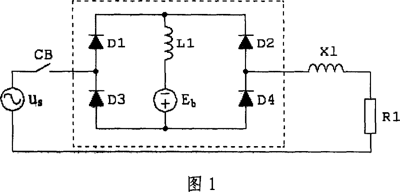
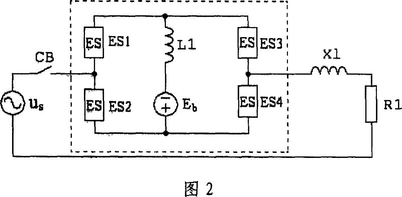
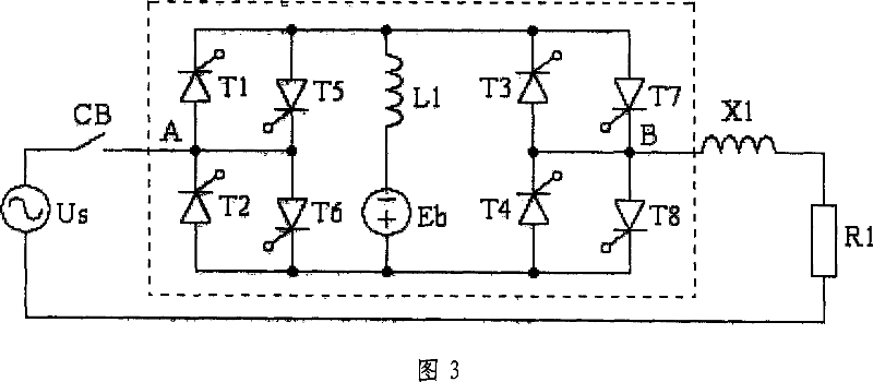
[0020] Embodiment 1, as shown in Figure 3, the fault current limiting device based on the rectifier bridge and bidirectional switching, including a bridge composed of electronic switches ES1, ES2, ES3 and ES4, a DC current limiting reactor L1 and a DC bias power supply Eb; wherein, one end of the electronic switch ES1, one end of the electronic switch ES3 and one end of the DC current-limiting reactor L1 are connected together; the other end of the DC current-limiting reactor L1 is connected together with the negative pole of the DC bias power supply Eb; One end of the switch ES2, one end of the electronic switch ES4 and the positive pole of the DC bias power supply Eb are connected together.
[0021] The two-way electronic switches ES1, ES2, ES3 and ES4 are all composed of two thyristors SCR connected in antiparallel. When the system is normal, control thyristors T1, T2, T3, and T4 to be in the normally-on state, and control T5, T6, T7, and T8 to be in the off state, then the...
Embodiment 2
[0022] Embodiment 2, as shown in FIG. 4 , is basically the same as Embodiment 1, except that the electronic switches ES1 and ES4 are bidirectional controllable electronic switches, and ES2 and ES3 are unidirectional controllable electronic switches. Under normal system conditions, the control switch tubes T1, T2, T3, and T4 are in the normally-on state, and T5, T6 are turned off. The bridge is in an uncontrolled rectification state. The function and characteristics of the current limiter in the circuit are the same as the above example. When a short-circuit fault occurs, the current in L1 rises rapidly. When it is detected that the current of L1 is greater than a certain set value, the control turns off T2 and T3 and turns on T1, T5, T4, and T6, then L1 is connected in series to the AC circuit, and L1 can limit the steady-state value of the short-circuit current in the AC circuit . This circuit has used two tubes less than the scheme shown in accompanying drawing 3. After a ...
Embodiment 3
[0023] Embodiment 3, as shown in FIG. 5 , is basically the same as Embodiment 2, except that in this solution, the controllable bidirectional electronic switch can only be controlled in one direction, and the other direction cannot be controlled. Under normal circumstances, control T2 and T3 to turn on, and T1 and T4 to turn off, then D1, D2, T2 and T3 form an uncontrolled rectifier bridge. After the short-circuit fault occurs, turn off the T2 and T3 tubes, control the T1 and T4 tubes to be in the normally-on state, and then the inductor L1 is connected in series with the AC circuit to limit the steady-state value of the short-circuit current. The parameter calculation of this circuit is the same as that shown in Figure 4, but it is simpler and the cost is lower.
[0024] In the above solution, the controllable electronic switch adopts a silicon controlled rectifier or a combination of a silicon controlled rectifier and a diode, or a self-turn-off device, such as IGBT, IGCT, G...
PUM
 Abstract
Description
Claims
Application Information
 - R&D
- Intellectual Property
- Life Sciences
- Materials
- Tech Scout
- Unparalleled Data Quality
- Higher Quality Content
- 60% Fewer Hallucinations
Browse by: Latest US Patents, China's latest patents, Technical Efficacy Thesaurus, Application Domain, Technology Topic, Popular Technical Reports.
© 2025 PatSnap. All rights reserved.Legal|Privacy policy|Modern Slavery Act Transparency Statement|Sitemap|About US| Contact US: help@patsnap.com


