Adjusting and control method for the generator unit and reactive power compensator at the middle layer of self-control of the static mixed voltage

A technology of generator set and compensator, which is used in reactive power compensation, reactive power adjustment/elimination/compensation, AC network voltage adjustment, etc.

Inactive Publication Date: 2007-09-12
TSINGHUA UNIV
View PDF0 Cites 7 Cited by
  • Summary
  • Abstract
  • Description
  • Claims
  • Application Information

AI Technical Summary

Problems solved by technology

Therefore, maintaining the system voltage level, improving the voltage quality and maintaining the voltage stability of the system has become a very challenging issue

Method used


Image

  • Adjusting and control method for the generator unit and reactive power compensator at the middle layer of self-control of the static mixed voltage
  • Adjusting and control method for the generator unit and reactive power compensator at the middle layer of self-control of the static mixed voltage
  • Adjusting and control method for the generator unit and reactive power compensator at the middle layer of self-control of the static mixed voltage

Examples


Embodiment Construction

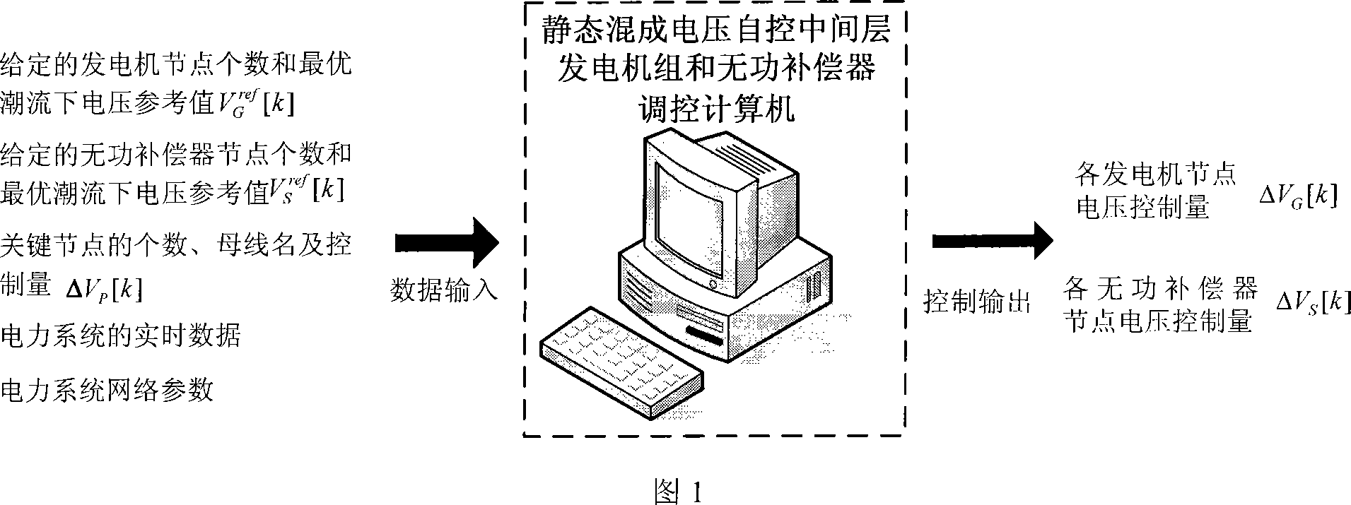
[0056] The main implementation of the regulation method of the static hybrid voltage self-control interlayer generating set and the reactive power compensator proposed by the present invention is shown in FIG. 1 .

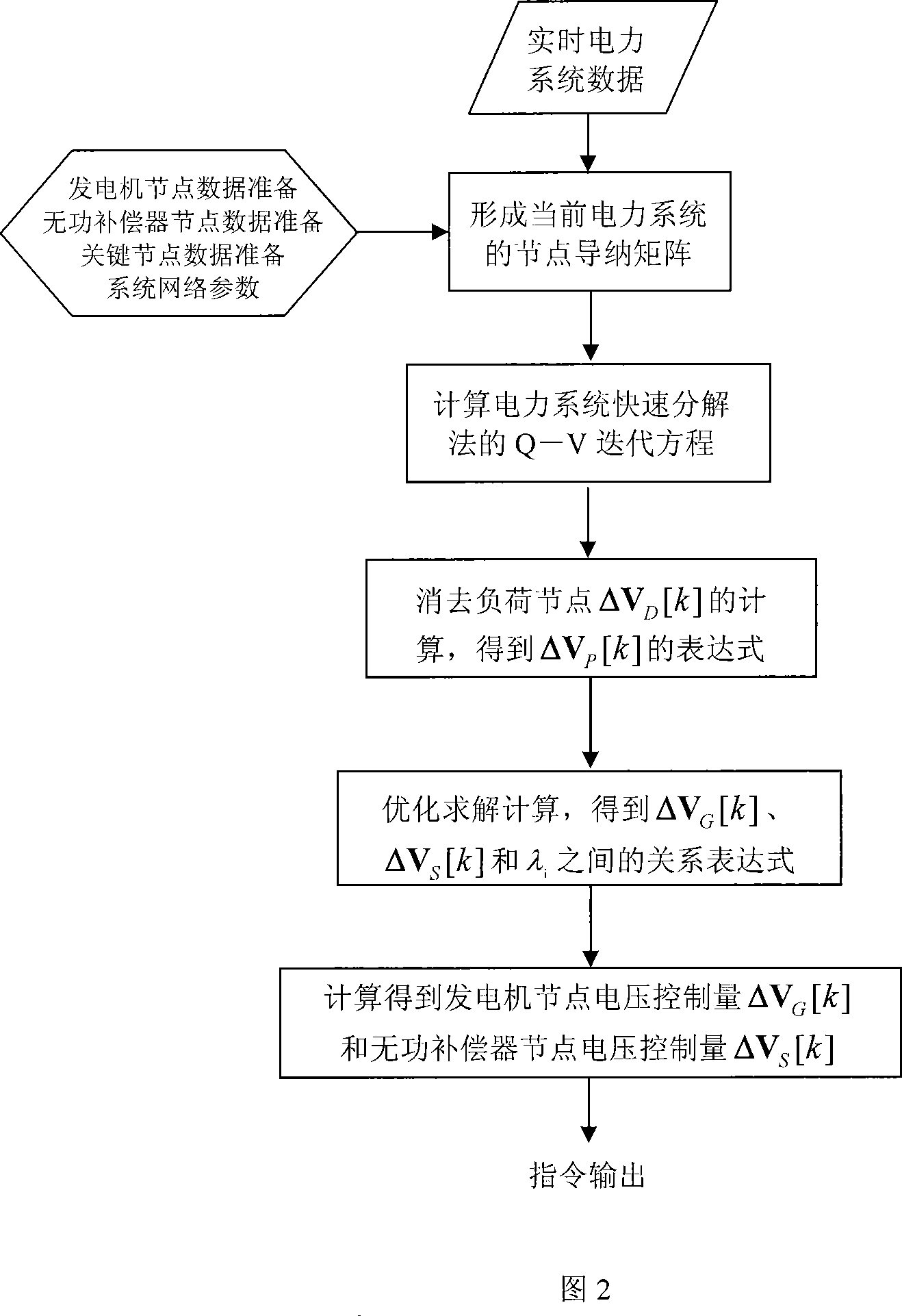
[0057] The present invention is implemented according to the following stages (flow process is referring to Fig. 2):

[0058] Step 1: In the offline state, give the indicators of the power system related to voltage quality, voltage security, economic operation, etc.: (a) given the network parameters of the power system; (b) given the number of key bus nodes α P And the corresponding bus name, and the control value ΔV of each key bus node Pi [k]; (c) given number of generator nodes α G and the number of reactive power compensator nodes α S , and each generator node voltage reference value V under the given optimal power flow Gm ref [k] and the voltage reference value V of each reactive power compensator node Sn ref [k];

[0059] Step 2: The node admittance ma...


PUM


Abstract

The invention belongs to the field of power grid reactive automatic control technique, characterized in that: at the same time of making fixed value control on node voltage of key bus line, using optimization algorithm to make optimization control on voltages of each generator node and reactive compensator nodes to make their set voltages close to the reference values calculated by optimizing power flow so as to assure safe-stable-economic coordinated optimization of voltage of power system.

Description

technical field [0001] The technical invention belongs to the automatic control method of voltage and reactive power in large-scale regional power grids, provincial power grids and regional power grids of power systems. Background technique [0002] The development of the power system has prompted people to make continuous efforts to improve the security and stability of the power system, especially the emergence of the power market has put forward higher requirements for the stability of the power system, and has brought new challenges to the safe and stable operation of the power system. features. Generally, power plants are far away from the load center, but due to factors such as economics and environmental protection, on the one hand, the development of some power networks cannot keep up with the needs of the rapid growth of power loads, making some transmission lines in a state of heavy load or overload operation; on the other hand On the one hand, the implementation ...

Claims


Application Information

Patent Timeline
Patent Type & Authority Applications(China)
IPC IPC(8): H02J3/00H02J3/12H02J3/18H02J3/38H02J3/46
CPCY02E40/30
Inventor 胡伟梅生伟陈颖张雪敏卢强
Owner TSINGHUA UNIV
Why Eureka
Try Eureka