AVS-M video coding fast motion estimation method based on the in-block down-sampling
A fast-moving, video coding technology, applied in digital video signal modification, TV, pulse modulation TV signal transmission, etc., can solve the problems of increased number of matching searches and huge amount of calculation, and reduce the amount of calculation and complexity of calculation , The effect of improving coding efficiency
- Summary
- Abstract
- Description
- Claims
- Application Information
AI Technical Summary
Problems solved by technology
Method used
Image
Examples
Embodiment 1
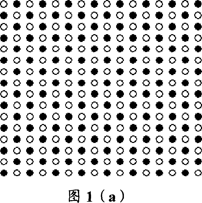
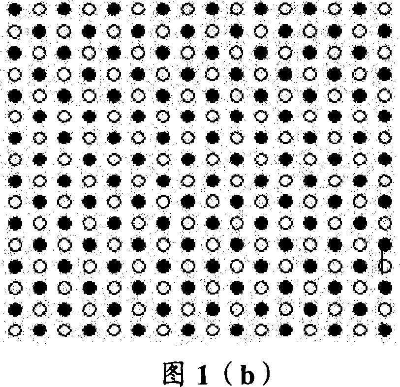
[0042]Fig. 1(a) is a schematic diagram of down-sampling of the first pixel interval of a block of 16×16. The black dots in the figure represent the pixels involved in the SAD operation, and the colorless dots do not participate in the operation. As shown in Figure 1(a), in the video compression algorithm using the SAD criterion for block matching, for the defined block 16×16 (that is, 16 lines per block, 16 pixels per line) pixel block division mode, The calculation is carried out by sampling the pixel points at intervals in the block, that is, in the matrix arrangement of pixel points in the block, the pixels in each row and column are sampled at intervals, and according to the following formula (A) Calculation:
[0043] SA D ′ = Σ i = 0 M 2 - 1 ...
Embodiment 2
[0056] The difference from the first embodiment is that the defined pixel block division mode is 16×8 blocks, that is, each block has 16 rows, and each row has 8 pixels.
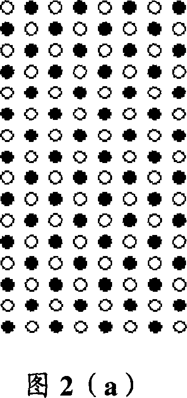
[0057] Figure 2(a) and Figure 2(b) are schematic diagrams of downsampling of the first and second pixel intervals of the block 16×8, respectively. The black dots in the figure represent the pixels involved in the SAD operation, and the colorless Points do not participate in the calculation. The difference between Fig. 2(a) and Fig. 2(b) is: in the matrix arrangement of pixels in the block, the sampling pixels corresponding to the rows and columns are reversed.
[0058] The formula used in Figure 2(a) is:
[0059] SA D ′ = Σ i = 0 7 Σ j = 0 3 ( ...
Embodiment 3
[0064] The difference from the first embodiment is that the defined pixel block division mode is 8×16 blocks, that is, each block has 8 rows, and each row has 16 pixels.
[0065] Fig. 3(a) and Fig. 3(b) are schematic diagrams of the downsampling of the first and second pixel intervals of the block 8×16 respectively. The black dots in the figure represent the pixels involved in the SAD operation, and the colorless Points do not participate in the calculation. The difference between Fig. 3(a) and Fig. 3(b) is: in the matrix arrangement of pixels in the block, the sampling pixels of the corresponding rows and corresponding columns are reversed.
[0066] The formula used in Figure 3(a) is:
[0067] SA D ′ = Σ i = 0 3 Σ j = 0 7 ...
PUM
 Abstract
Description
Claims
Application Information
 - R&D
- Intellectual Property
- Life Sciences
- Materials
- Tech Scout
- Unparalleled Data Quality
- Higher Quality Content
- 60% Fewer Hallucinations
Browse by: Latest US Patents, China's latest patents, Technical Efficacy Thesaurus, Application Domain, Technology Topic, Popular Technical Reports.
© 2025 PatSnap. All rights reserved.Legal|Privacy policy|Modern Slavery Act Transparency Statement|Sitemap|About US| Contact US: help@patsnap.com


