
Stack crane and driving control method thereof

A crane and stacking technology, applied in the direction of lifting device, storage device, transportation and packaging, etc., can solve the problems of acceleration limitation, complicated structure and control, and high cost.

Active Publication Date: 2007-09-19
MURATA MASCH LTD
View PDF2 Cites 16 Cited by
  • Summary
  • Abstract
  • Description
  • Claims
  • Application Information

AI Technical Summary

Problems solved by technology

However, from the start of the stacking crane until the electromagnetic clutch is energized to make the roller act as a brake, it is driven only by the lower motor. Therefore, especially when the stacking crane is started, there will be a large inertia acting on the main column, and the acceleration will be limited. , which in turn leads to a lower startup rate
In addition, the structure and control for adjusting the verticality of the main column of the stacking crane when it is stopped are cumbersome, and the cost tends to increase

Method used


Image

  • Stack crane and driving control method thereof
  • Stack crane and driving control method thereof
  • Stack crane and driving control method thereof

Examples


Embodiment Construction

[0038] Embodiments of the present invention will be described in detail below with reference to the accompanying drawings.

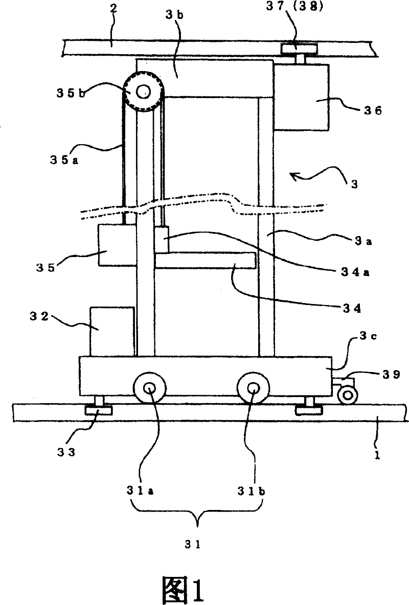
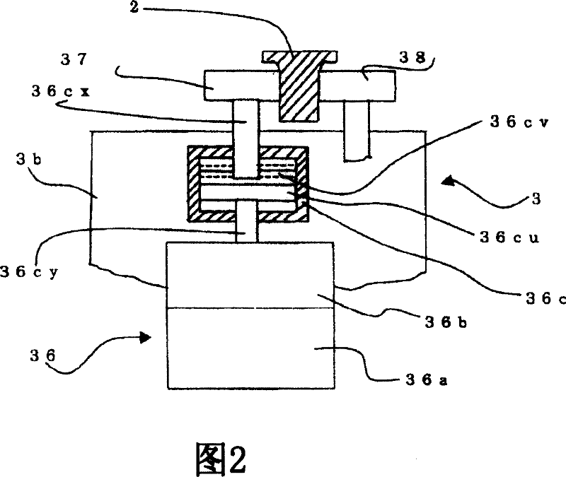
[0039] In Fig. 1, 1 is a guide rail for traveling the stacking crane, and 2 is a guide rail for guiding the upper frame of the stacking crane. They are respectively laid along the prescribed path in the stacker. The stacker is arranged vertically and horizontally to store wafers, etc. Shelves for FOUP storage of substrates. 3 is a stacking crane, the main body of which includes: a column 3a extending in the vertical direction, an upper frame 3b and a lower frame 3c respectively provided at the upper and lower ends of the column 3a.

[0040] 31 is a running wheel, which includes a driving wheel 31a and an idler wheel 31b, which are supported by the lower frame 3c and can run on the guide rail 1 for traveling of the stacker crane. 32 is the 1st driving mechanism, has motor, deceleration mechanism and brake, is transmitted power to driving wheel 31a by the...


PUM


Abstract

The invention provides a stack chain block and a driving and controlling method thereof. The stack chain block is capable of moving along an upper side guide track and a lower side guide track. An upper portion of a main body is clamped with the upper side guide track and can move relatively to the upper side guide track. A lower portion of a main body is clamped with the lower side guide track and can move relatively to the lower side guide track. A column is extended and provided along a vertical direction, and connects the upper portion and the lower portion of the main body. A lifting body can be moved along the column up and down. An upper side driving device is arranged at the upper portion of the main body, limits the upper portion of the main body relatively to the upper side guide track, and makes the upper portion of the main body move along the upper side guide track. A lower side driving device is arranged at the lower portion of the main body, and makes the lower portion of the main body move along the lower side guide track. A controlling portion inputs a first signal representing a target speed or a target position into the upper side driving device and a lower sidedriving device, so that moving speeds of the upper portion and the lower portion of the main body are equal, the controlling portion inputs a second signal to the upper portion driving device after movement of the upper portion of the main body is finished and during stopping the lifting body, the second signal releases limitation of the upper driving device on the upper side guide track.

Description

technical field [0001] The present invention relates to a stacker crane installed in a stacker crane for temporarily storing and storing intermediate products in the manufacturing process due to process time adjustments, etc. . Among them, it relates to a high-rise stacking crane installed in a high-rise stacker. Background technique [0002] In the layout of the clean room of a typical semiconductor factory, multiple inner-process circular tracks and inter-process tracks connecting these multiple internal-process circular tracks are laid, and are adjacent to the inner-process circular track and the inter-process track. Semiconductor processing equipment that performs a series of processing (thin film formation, photolithography, cleaning, etching, inspection, etc.) on substrates such as wafers, and stackers that temporarily store substrates during processing. Normally, substrates such as wafers are stored in dedicated storage containers that protect them from dust, such a...

Claims


Application Information

Patent Timeline
IPC IPC(8): B66F9/07B66F9/24
CPCB65G1/0407B65G1/0421B65G1/10B66F9/07
Inventor 村田正直山路孝椿达雄
Owner MURATA MASCH LTD
Learn More